|
Steam Car Network
|
THE RUSCOMBE GENTLEMANS STEAM BICYCLE5/20/2020 THE RUSHCOMBE GENTLEMAN'S STEAM BICYCLE BY MARK DRAKE 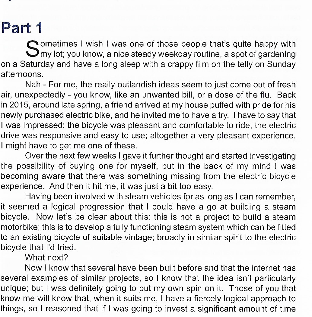   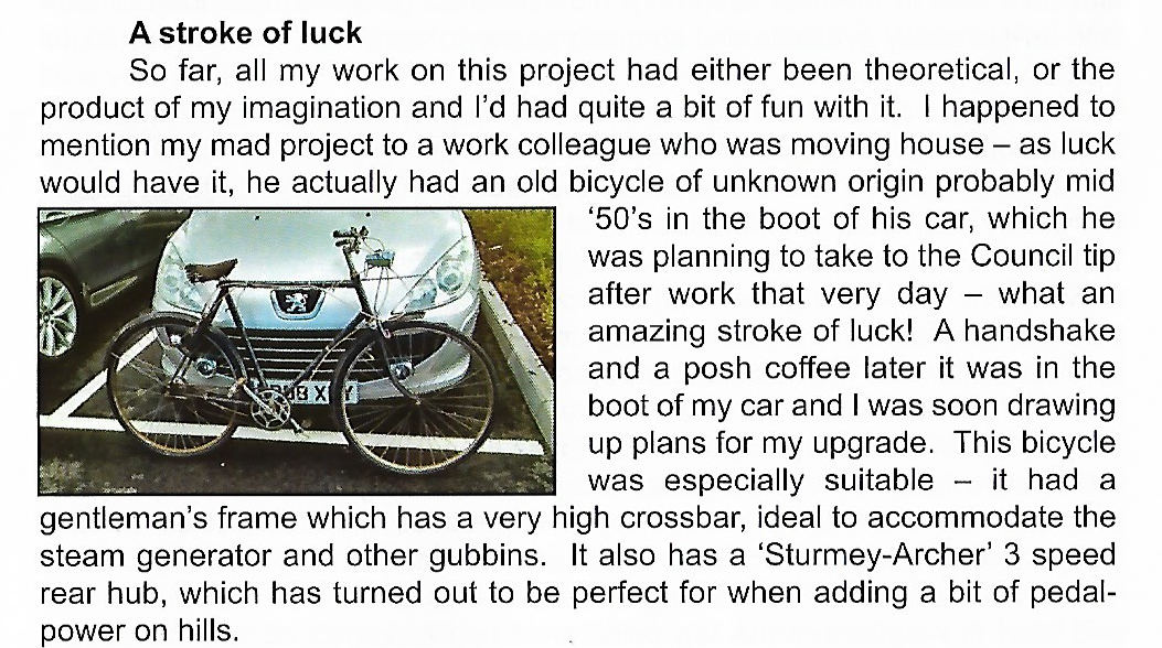 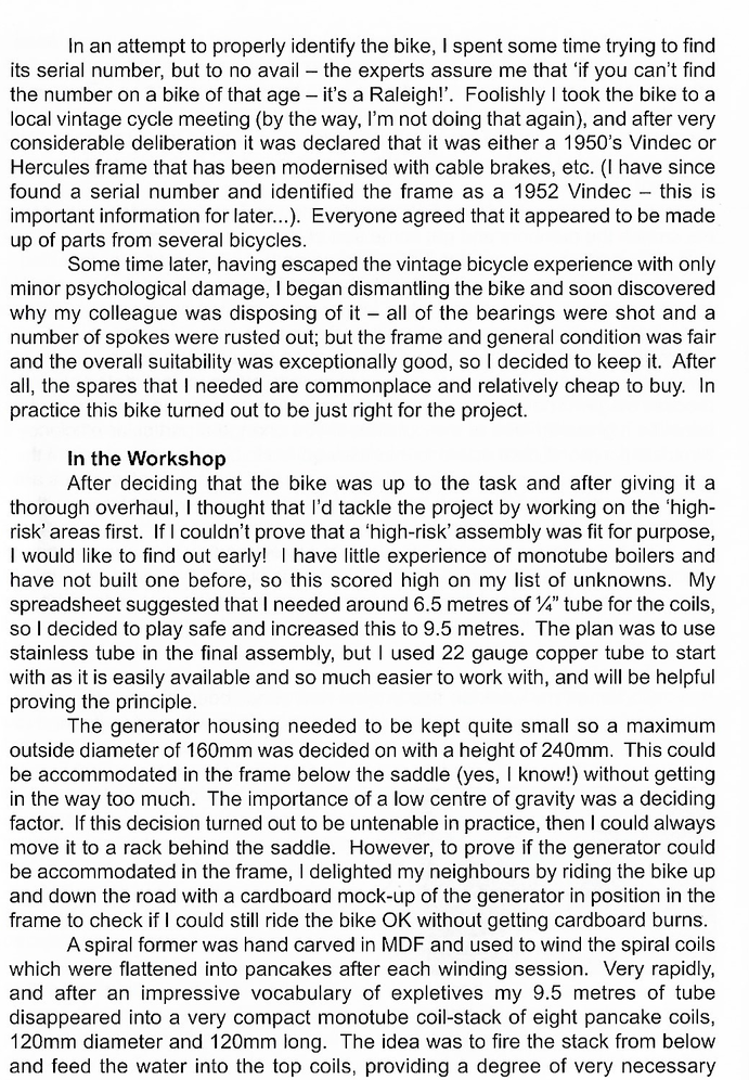 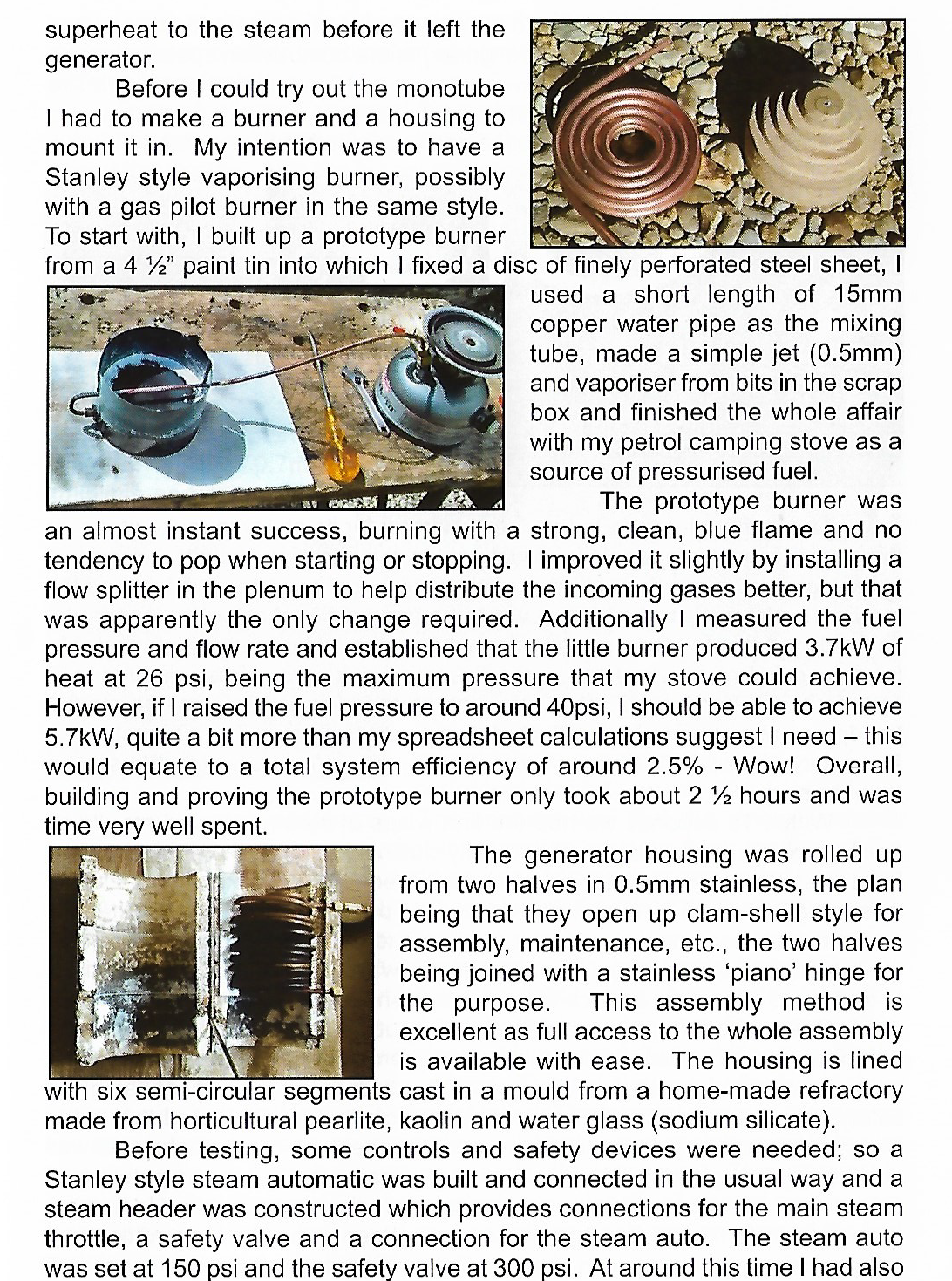 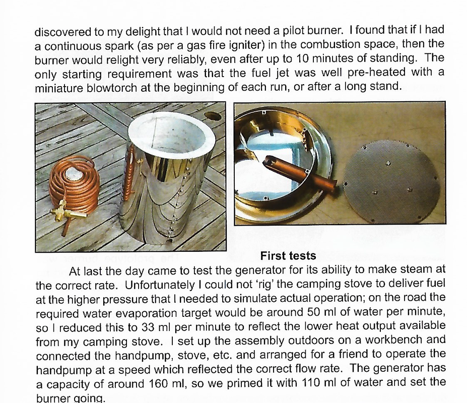  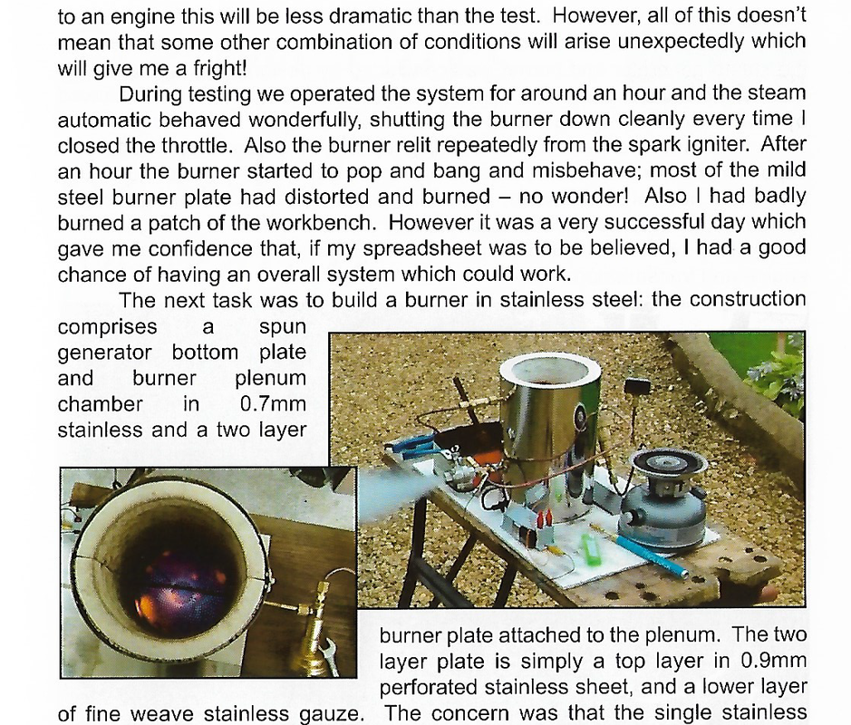 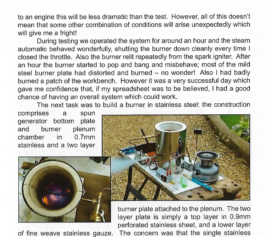  
0 Comments
Steam engines4/16/2020 FLYING STEAM ENGINESHomeHistoryMy Recent EffortsGenerating the SteamFuelDesigns for aircraftHydroplanesPracticalSkylarkI.C. EnginesCompressed Air
Conventional boilers In their simplest form a boiler is a round tank of water with a fire underneath and in the case of my first engine (designed in 1967 by David Parker) it is little more than that.  What we can do with these little boilers is to improve on the material normally used on model locomotives and to look at just how big a safety factor we really need. Model locomotives sometimes have a boiler shell that is twenty, thirty, even forty times stronger than it needs to be! ! The modern aircraft which we happily board and in which we fly away on our holiday works very safely on much lower factors of mechanical strength than forty to one! It is really quite safe to use a factor of four to one on a boiler of only 50 mm diameter which operates at perhaps 150 C. David's 'Comet' engine (see photograph and drawings) has a quite generous safety factor of 5:1 and the boiler is free of any long term danger due to corrosion. The boiler is made of 0.5mm nickel silver sheet, silver soldered with very simple water tubes of 6mm copper to increase its heating surface. It is spirit fired and I hydraulically tested mine to 3 times the working pressure with no problems, it worked consistently for over five years. What we can do with these little boilers is to improve on the material normally used on model locomotives and to look at just how big a safety factor we really need. Model locomotives sometimes have a boiler shell that is twenty, thirty, even forty times stronger than it needs to be! ! The modern aircraft which we happily board and in which we fly away on our holiday works very safely on much lower factors of mechanical strength than forty to one! It is really quite safe to use a factor of four to one on a boiler of only 50 mm diameter which operates at perhaps 150 C. David's 'Comet' engine (see photograph and drawings) has a quite generous safety factor of 5:1 and the boiler is free of any long term danger due to corrosion. The boiler is made of 0.5mm nickel silver sheet, silver soldered with very simple water tubes of 6mm copper to increase its heating surface. It is spirit fired and I hydraulically tested mine to 3 times the working pressure with no problems, it worked consistently for over five years.My experience with 'Comet' has led me to believe that it is perfectly feasible to build a model speed boat engine along similar lines as the airborne engine. Add reversing gear and a throttle valve and you could build a fast planing steam boat that is quiet, controllable and above all absolutely unique.. This is not silly thinking, the Comet's engine directly coupled to a 12''x8'' propeller turns at 3200 RPM. and develops, a static thrust of about 600 grams. The weight of this engine and boiler is little more than a 540 size electric motor and a standard 7cell 1500 ma Ni/Cad battery pack. The fastest steam powered model boats in the world are the tethered flash steam hydroplanes which reach speeds of up to 170 kph this brings me to a different kind of boiler that offers huge improvements in performance for model aircraft, the flash or Monotube Steam Generator. Small monotube theory and practice What is Flash Steam? There are two basic ways of generating high pressure steam almost everyone is familiar with the locomotive boiler and the land and sea born variants of the pressurised container, heated with either water or fire tubes and an external source of heat. In a flash boiler the heating surface is a single or it may be a series of tubes into which the cold feedwater is pumped against the developed pressure. The heat source is usually an oil, petrol, or gas flame directed against the tube. The tube is normally coiled and housed in a thin light weight case of stainless steel and the flame is directed through the centre of the coil. The development of high pressure steam is virtually instantaneous, hence the term flash steam. The little Groves 1936 engine that I have built goes from cold to full power in 8-10 seconds and the power is turned out all the time there is water and fuel. Throttling works within fairly narrow limits just by turning the heat supply down, the response is instant. The narrow band of power available can be satisfactorily extended using a more elaborate control system. The Groves engine is very simple and intended for free flight only where one power setting is all that is needed. The steam so generated can be superheated to the point of the engine's self distruction, where the lubricating oil is turned into carbon before it reaches the cylinder walls. I am fascinated by monotubes and in 2002 when the offer came I could not resist the temptation to buy all 15 feet of Skylark with its oil fired Monotube steam source. Like all experimenters I had to get it going ASAP in search of the first modification or improvement I could introduce. I am quite sure the previous owner would have been disappointed in me if I hadn't! There was one major departure from normal monotube practice; it was not a monotube at all it was a bi-tube, two parallel tubes wound alongside each other. (There is a theoretical advantage in doing this which I will not go into at this point.) I have no complaint about Skylark, I launched her in the Chichester Ship Canal in April 2003 and everything operated much as the previous owner had said it should except, try as I might all I could get was 25psi and a slow walking pace. I was told that Skylark steamed well at 80-100psi and produced enough power to run at full hull speed which should be say 3.5mph, a fairly good walking pace. That is, it did when it had a monotube. I tried all I could to get that bi-tube to operate but it would not play ball. The previous owner gave me his bi-tube pressure equalising valve along with Skylark when I bought her and I experienced no sign of overheating of one tube with the other tube running much cooler. I can look down the funnel straight into the flame area and if anything is red hot I can see it at once. My impression is it did divide the flow exactly as intended. All I got was 25psi. After a few weeks I gave up and made a new monotube from the self same two 20 foot (6.1 M) lengths of 3/16" (4 mm) Kunifer (copper alloy) brake pipe. They were joined with a screwed compression joint some way up the chimney out the way of the direct heat of the flame. Result, 60 psi whoopee progress! (At this point I changed the propeller for a bigger one and as expected the pressure rose because the load was greater and now the boat operated exactly as its builder described. This matter of Balance between load and heat input will be covered under "Controls" when I write it!) I do not think it was the bi-tube as a device that was the problem, my firm belief is that by switching from bi-tube to monotube I had DOUBLED the velocity of the feed water through the 3/16" (4 mm) Kunifer tube. This matter of water velocity has been discussed in the book "Experimental Flash Steam", it is so relevant to these notes that I have included the results in my table, I quote verbatim from the book:-. Quote from Experimental Flash Steam, by Benson and Rayman my copy being published by Argus Books Ltd in 1973. The Experiments themselves were carried out by Mr Edgar T Westbury one of the most well known writers and designers of model engineering projects in UK. He is known the world over, the world of model engineering that is; (not a very big world!). Page 59. “Tests carried out on three copper boilers each 11 Feet in length and 3/16" (4 mm), 1/4" (6.3 mm) and 5/16" (7.9 mm) diameters respectively and with a wall thickness of 0.03" (0.7 mm). Each coil was wound upon a circular tapered form, 2 1/4" (57 mm) inside diameter down to 1 1/2" (38 mm) diameter and spaced 1/8" ( 3.2 mm) apart. The casing left 1/8" (3.2 mm) gap at the largest coil. Water was fed from a water pump driven by an electric motor. Each boiler was fired by the same air-gas blowpipe 1 7/8" (48 mm) diameter, and various evaporation tests were conducted with a spring loaded outlet valve set to blow at 500psi. In each test the 3/16" dia. boiler gave the best results and on a maximum evaporation test managed 27 cu. Inches per minute with the gas blowpipe flat out and the steam highly superheated. This represents about 1 lb per minute and seems a remarkable figure for only 11 feet of tube and the fact that this boiler had the lowest heating surface. In every test the 5/16" boiler gave the worst results. On repeating the experiments using thicker walled tube the relative results were confirmed but evaporation increased by about 12%! End of quote. E.T. Westbury's test results on 3/16" tube is included in the table which follows. SO what is going on? 60lbs of highly superheated steam per hour from about 1/2 sq. ft heating surface! It must be said at once that this sort of hard driven performance is VERY wasteful of heat using only a few hundred degrees Centigrade from the flame. A Gas-Air torch typically burns at about 2200 degrees C at the flame cone. A thin piece of steel wire at the outlet to my tiny boilers glows red, about 800-900 C. We do not want red hot exhaust on a steam boat and I certainly do not get it on Skylark. Why is velocity so obviously critical in the performance of monotubes? The previous owner of Skylark has a theory which I believe to be correct. As the water flows and heats at some variable point along the tube it begins to form tiny steam bubbles on the inside wall. These must tend to stick to the surface just as they do to the bottom of a saucepan when you boil water in it. The steam bubbles seem obstinately glued to the metal. In order for a monotube to operate efficiently the water must flow fast enough to scour bubbles away IMMEADIATLY they form. The conductivity of any vapour is thousands of times worse than water and maybe 100,000 times worse than copper alloys like Kunifer. If as I believe the dramatic increase in performance is due to the increased water velocity then I thought maybe I can juggle a few numbers and come up with a very interesting, if empirical figure that represents a likely MINIMUM velocity to aim for when designing very small monotubes like Skylark's and the really tiny tubes I have in Tiddler's Monotube. Another result of this scouring is that scale and oxides do not form on the inside of the tube. Indeed if you cut open a well used section of a monotube you will see that the inside surface looks as if it had been lightly etched.  I could have directly compared the results of the bi-tube and monotube and left it at that but in addition to Westbury's 3/16" diameter tube experiment, a further source of data is available in an article published in the Model Engineer magazine in 1992. I could have directly compared the results of the bi-tube and monotube and left it at that but in addition to Westbury's 3/16" diameter tube experiment, a further source of data is available in an article published in the Model Engineer magazine in 1992.  This was written by Bob Kirtley covering in great detail the construction of his world record breaking hydroplane Pisces II which raised the Class B Steam record from about 80 mph to 104 mph in one step. I have seen her go and it is a joy to behold, the noise is like no other, music to my ears and any other Monotubist's. This was written by Bob Kirtley covering in great detail the construction of his world record breaking hydroplane Pisces II which raised the Class B Steam record from about 80 mph to 104 mph in one step. I have seen her go and it is a joy to behold, the noise is like no other, music to my ears and any other Monotubist's.What I did was to compare directly the water velocities of the four separate cases and tabulate them as follows. The different values for Monotube area (Ma) for Pisces and Westbury are because of the differing tube wall thickness. Boiler Details ParameterSkylark Bi Tube 3/16” Dia.Skylark Monotube 3/16” Dia.Pisces II Monotube 3/16” Dia.Westbury Test Monotube 3/16” Dia.Pump Ram Diameter (D)0.953cm0.953cm0.653cmN/APump Stroke (S)1.80cm1.80cm1.27N/AStroke/ minimum (Sm)300300cm2500N/AVolume/ minimum (Vm)384cc384cc1002cc440cc see textMonotube area (Ma)0.141cm20.075cm20.103cm20.081cm2H2O Velocity (WV) =Vm/Ma384/0.141 2723cm/min384/0.0705 5446cm/min1002/0.103 9728cm/min440/0.081 5432cm/minW V Metres/min)27.2354.4697.2854.32 It was with smug satisfaction that I noticed the close tally between Skylark and the Westbury test data. To other Monotubists everywhere please give me the current particulars of your system so we can acquire a data bank for future use by others. All the tabled parameters plus pressures, temperatures, fuels, burners anything you can think of that may help others who will follow on after us. I don't pretend that my observation and experience is a scientific study but it may prove more concrete than any other data that I have seen to date. It is further born out by the fact that if I slowly reduce the heat input setting on Skylark there comes a point at about 50 psi when the pressure drops very quickly from 50 to 25 psi; without a commensurate reduction in fuel flow. With the available data I would suggest that anyone contemplating a small monotube design for normal cruising speeds and pressures a WATER INPUT VELOCITY of about 50 metres per minute (0.8 Metres per second) should be a safe minimum to aim for at the systems normal 'cruising' power. The importance of the above statement cannot be over emphasised as I believe it may be the key to solving much of the hit and miss approach that seems to dog this subject and is perhaps the root cause of the commonly heard mystique surrounding design and application of very small monotube steam plants. To design a plant we can now start from the same point as steam plant designers have always started; the steam consumption, this basic calculation is very clearly explained elsewhere in text books and I spare myself the need to repeat it here. This value can also be gained from users of the same and similar engine designs of course and it is perhaps a more reliable guide as well! In any case it is a good way of checking your own calculations. From the mass of steam reguired per hour the pump ram diameter and stroke can be decided and then the tube bore for a given water feed velocity becomes an additional but simple calculation. From my experience with Skylark and tiny monotubes for aircraft models I can suggest that it is an advantage if the water feed velocity drops well BELOW 0.8 metres per second for slow speed work, maybe as low as 0.4. I still get a reliable flow of steam at maybe 80 revolutions per minute but it is wet, as one would expect but very controllable. This study, whilst interesting may be of very limited use much outside of the tube diameters in the table, I would hazard a guess that all would be well up to 3/8" (9 mm) bore tube. I have done some calculations on turbulant flow at the temperatures and pressures at which Skylarks monotube normally cruises and it seems to be that turbulent flow will occur at all the water flow rates we are likely to work at and it is unlikely to fall outside that rule of Thumb up to maybe 3/8" (9 mm) bore. More is needed in this arena to prove anything. It may just be that in full size practice perhaps the known point of turbulence is the lower end of any particular monotube's efficient and useful working range. Do we have a proffessional Monotubist out there ready to help us? At this point it may be of interest to put a few figures together to illustrate what this all means to me. Skylarks boiler certainly produces about 50 lbs. of steam per hour at 100 psi and it is reasonably dry, the bore of the tube is 3mm (7square mm area) and there is about 10 metres of tube in the flame area. Now if we double the diameter of the bore from 3 to 6mm the area quadruples to 28 square mm and at about 1 metre per second water velocity you will get 200lbs of steam at 100 psi and I would expect you could do this with only 10 metres of tube if you throw enough heat at it. However more tube of greater diameter added as a feed water heater if you like to separate the sections mentally, will give a very good return in higher efficiency. This is exactly how Doble and others built their car monotubes; I am confident they knew exactly what they were doing and why! Looking at Dobles monotubes they had about 25- 30% of tube length at the smallest diameter and usually had a total of three diameters of tube in the furnace which must have helped reduce pumping frictional effort by perhaps 30-50%. When I build a bigger monotube I will do exactly what the old masters did. Pisces has a water velocity twice that in Skylark and produces at least eight to ten times the power. I know this because Class B boats have similar rules be they Steam or IC Powered, the IC boats are usually fitted with 30cc racing two stroke glow motors which are known to be capable of 5 HP. A point I must make here Bob Kirtley's engine has a displacement of 13cc and yet has a performance comparable with 30cc IC engines!. A good steam Hydro is not that much slower than an IC boat and yet is generally 2-4 lbs heavier. I doubt if Skylark needs more than half a horse power to drive her as she goes at the moment. Some Monotubes go and others Don't The simple analysis given above is I believe the key to first time success in the construction of a small steam generator that performs in a very satisfactory manner and one that doesn't. I have seen on the net and in books many notions and designs, one of which involved the use of 300 feet of 1/4" copper tube to run a Stuart 5A, Westbury's experiment proved that tube length alone is not the answer to success in making steam but it must have a place in raising overall efficiency. In some discussions about flash boilers the separation from a feedwater heat function and the steam raising and superheating area is viewed as a physical point of some mystic significance. If you look at Doble, White and Serpollet cars they certainly were efficient but never as far as I am aware did any of these great engineers write about the critical nature of water velocity at that transitional stage where the absorbtion of the latent heat takes place. Nor do they seem to consider that point of any significance in their designs. Their boilers had long lengths of tube of several diameters and ended up with a section where the velocity certainly was in excess of a metre per second. Without experiment into this we will never know the point where transition from liquid to gas takes place and how dynamic the change of that point along the tube will be as power (heat input) is changed by the operator; and having discussed it before with others and thought about it at length; I don't think it matters one jot! Of one thing I am certain, once the smallest bore tube has been reached that tube section must remain the same until it reaches the engine. I have seen set ups where the steam leaves the monotube and goes into manofolds and convoluted passages and is therefore allowed to expand cool and slow down as it gets to the engine----Why? Why do that? One answer I got was, "Well to me it is obviously being too hopefull expecting the steam to get to the engine through that tiny tube"! To my mind it has already gone through 30 or more feet of it, what effect is another two feet going to have? The small tube loses heat far slower than big tube and it is far more efficient to lag that diameter so my 4 mm steam tube goes straight to the steam chest. Get the steam to the engine ASAP and let as much expansion as possible take place there rather than en route, that is my view at the moment. The crucial thing is in the design of the heat source, there is obviously an area/volume where the heat will be the most intense and that is where the small bore section has to be. If the water begins to vapourise in the feedwater heater so what, it will soon be accellerating along the hot bit and it won't stay liquid for long. When I fit the feedwater heater section it will be up what is now the funnel; it will be 6mm or 8mm tube and will be fed through a cone into the 4mm diameter tube until it gets to the steam chest. This brings me back to the question of tube length. The longer the tube, the more heating area = greater efficiency. Yes, but there are limitations and in small sizes pumping effort is a very significant limitation. I want to try a feedwater heater section above the monotube in the smoke stack and because this area is unlikly to have boiling water in it, feedwater velocity is of much less significance. This then permits the use of bigger bore tube for the feedwater heating section of the system which will help with reducing pumping effort. Accepting that there is NO WAY of predicting where along the tube the water actually boils from measurement the exhaust temperature at the chimney top is only about 300 C. and boiling point at 100 psi is about 170 C. it is far less likely to boil water in the chimney than right in the fire. That is as far as the argument needs to go in my view. The relative merits of flash or conventional Boiler Conventional boiler merits. 1. The containment of a mass of heated water makes power control as simple as a carburettor on an IC engine. 2. The complications of pumps and pump control on a flash plant make the conventional boiler more reliable especially in the smallest sizes. 3. Pressure control in a heated pressurised tank, using a safety valve is essential for safety and very useful when throttling with a simple valve. 4. The pressure controlled tank of heated water is a store of instantly available energy in its latent heat. This latent heat is the source of the destructive power of a conventional boiler explosion. Disadvantages. 1. Requires regular pressure testing. 2. Is heavier than any self respecting flash unit of the same power. 3. Limited in its capacity to safely contain very high pressures and temperatures The Latest Monotube I have Built The pictures in this paragraph depict a monotube I built quite recently for use by a student at Southampton University and I make no apologies for the fact that it is a bigger version of H H Groves typical airborne Monotube design.  The frame is of 1" x 1/16" 316 Stainless steel strip made to operate mounted in a vertical furnace of lagged stainless steel tube of about 5" bore. The most tedious job was striking all those slots in the spacers. I did this by mounting a 4mm thick angle grinder wheel in my off hand bench grinder and making a special tool rest which is grooved to support the thin material as it is cut. I wore out two wheels to get the job done which I thought was reasonable thin stainless is very hard on the wheel. I tried stacking all four up together and do them all in one go but it was far more hard work on the wheel and on me getting the cut made. The University TIG welded the frame together after I had tacked it with my Oxy/Acetylene. The frame is of 1" x 1/16" 316 Stainless steel strip made to operate mounted in a vertical furnace of lagged stainless steel tube of about 5" bore. The most tedious job was striking all those slots in the spacers. I did this by mounting a 4mm thick angle grinder wheel in my off hand bench grinder and making a special tool rest which is grooved to support the thin material as it is cut. I wore out two wheels to get the job done which I thought was reasonable thin stainless is very hard on the wheel. I tried stacking all four up together and do them all in one go but it was far more hard work on the wheel and on me getting the cut made. The University TIG welded the frame together after I had tacked it with my Oxy/Acetylene.The tube was 3/16 Dia. Copper/Nickel brake pipe which serves well enough as a monotube but I did melt the one I built for my little launch so the new monotube will be of Stainless Steel.  I thought the Stainless would be a frightful price but it was not much more than the brake tube! Twelve Metres of 4mm stainless cost £40 and the same length of Copper/nickel was going to set me back £28---no contest! I thought the Stainless would be a frightful price but it was not much more than the brake tube! Twelve Metres of 4mm stainless cost £40 and the same length of Copper/nickel was going to set me back £28---no contest!A new Monotube for Skylark The following pictures depict the new Skylark monotube as I built it and made the small adjustments necessary to make everything fit.  Frame Stretchers (3 of 4) The frame stretchers and rings are of the same 1" (25mm) x 16swg. (1.6mm) 316 st/stl. that I mentioned in the previous paragraph. The struts or Stretchers have to be cut with 30+ slots in their 16" (406mm.) length. The whole assembly is inserted into a piece of 4" (100 mm) Mild Steel tube which is well insulated with Mineral Wool and layers of alluminium foil. The heated core is 4" (100 mm) Diameter and the outer case of the boiler is 15.5" (340 mm) diameter giving a total of 5.5" (140 mm) of surrounding insulation  Stretchers, Rings and 2 clamp jigs The first two pictures shows the components of the frame, four spacer rings four vertical stretchers and two spacers which I made to hold the stretchers in position for welding. The third picture is the simple right angle section steel jig to which I clamp the rings and stretchers before welding. I have no TIG welder and I use Oxy/ Acetylene for all my stainless welding which of course uses much more heat in the process---which causes more distortion. Stretchers, Rings and 2 clamp jigs The first two pictures shows the components of the frame, four spacer rings four vertical stretchers and two spacers which I made to hold the stretchers in position for welding. The third picture is the simple right angle section steel jig to which I clamp the rings and stretchers before welding. I have no TIG welder and I use Oxy/ Acetylene for all my stainless welding which of course uses much more heat in the process---which causes more distortion.  Alignment Welding Jig Not surprisingly the biggest problem I found in making this particular frame WAS distortion; made much worse because I did not think about it enough! Last time, for Southampton University I just tacked it together using minimal tacks with Oxy/Acetylene, the University TIG welded it permanently which itself uses far less heat so there was very little distortion. Alignment Welding Jig Not surprisingly the biggest problem I found in making this particular frame WAS distortion; made much worse because I did not think about it enough! Last time, for Southampton University I just tacked it together using minimal tacks with Oxy/Acetylene, the University TIG welded it permanently which itself uses far less heat so there was very little distortion.  The complete new monotube Next time I may use a piece of tube to line the rings up and I will weld from ONE END. This will allow the weld to distort the stretchers as much as it needs to and permit correction as required before welding the next ring into position. Gas welding stainless is not a big problem but it uses a glass flux which goes black and is a devil to remove so the appearance of the finished product is not wonderful. However a furnace rarely improves the appearance of anything so this is not too much of a worry! It ended up reasonably straight and was a good fit in the furnace tube. The complete new monotube Next time I may use a piece of tube to line the rings up and I will weld from ONE END. This will allow the weld to distort the stretchers as much as it needs to and permit correction as required before welding the next ring into position. Gas welding stainless is not a big problem but it uses a glass flux which goes black and is a devil to remove so the appearance of the finished product is not wonderful. However a furnace rarely improves the appearance of anything so this is not too much of a worry! It ended up reasonably straight and was a good fit in the furnace tube. The hot end and concentric coilsI changed the design at this stage as a little arithmetic told me I could get the whole of one 20 foot (6 metre) length of tube into an inner core only 16" (400 mm) long less a metre or so for lead out length. Looking at typical albeit lightly blown oil heaters it is very noticable that the flame tongue streaks straight through the middle of the furnace space so this time I tried to pack as much tube in that area as I can. This is why the outer coils look a bit ragged and badly spaced because there was space to spare on the outside. I am convinced that how the tubes are presented to the heat source and how near optimum the fuel/air ratio is kept is very important to overall efficiency in monotube steam sources. The hot end and concentric coilsI changed the design at this stage as a little arithmetic told me I could get the whole of one 20 foot (6 metre) length of tube into an inner core only 16" (400 mm) long less a metre or so for lead out length. Looking at typical albeit lightly blown oil heaters it is very noticable that the flame tongue streaks straight through the middle of the furnace space so this time I tried to pack as much tube in that area as I can. This is why the outer coils look a bit ragged and badly spaced because there was space to spare on the outside. I am convinced that how the tubes are presented to the heat source and how near optimum the fuel/air ratio is kept is very important to overall efficiency in monotube steam sources.  How not to run Monotubes This is born out by the fact that in the steam model hydroplane, changing from one big burner to three smaller ones yielded more steam and higher speeds. Skylark's outer boiler casing was made by the previous owner who deliberately made it look as much like a coal fired boiler as he could, just for the fun of doing it, I may change it one day but for the moment I quite like the joke of explaining how little coal it uses! I have now made two cores for this boiler and each was smaller than the last and smaller than the one which was in the boat when I bought it. This is how and why I created space for so much insulation. All the added insulation and concentration of heat proved too much for this the second core in Skylark! The copper/nickel alloy monotube became blocked with black copper oxide powder and caused this failure which melted the tube and damaged the pressure gauge. It made a pop no louder than opening a can of lager and made me one of the worlds totally converted monotubists. The new core whilst more compact carries an identical length of tube about 36 feet (10 metres) actually in the fire, I have done this deliberatly to gauge any increase or loss of boiler efficiency that may be caused by the changes of monotube form and insulation. This latest core has modified form being of the same overall diameter but 2" (50 mm) shorter and with more tube concentrated in the centre, nothing else has been done of any significance. I really want to know what is going on in these steam systems. If this change betters things, the next change will be a blue flame burner then a chimney feed water heater. All being modifications of the same boat, engine and propeller. A Few Words about Materials The core of the new boiler is 100% stainless steel however even this remarkably heat resistant steel is no match for prolonged use at red heat and beyond. If you look at the burnt out end of the last monotube the case is made of stainless steel chimney liner which I thought might last 40 hours, it began to fail well before that and I had to fit another inner liner to prolong its life. The problem is much worse than in a racing hydroplane where the boiler may only be used for a few hours in a years testing and racing. I want 100 hours continuous use as a starting point. The outer case (or liner) was of 0.005" (0.12 mm) thickness and it began to fail after maybe 10 or 15 hours of use, the new liner is of 0.062" (1.6 mm) mild steel which has an inner liner of 0.024" (0.06 mm) Stainless steel protecting the first 6" (152 mm) of the hot end of the assembly. You can see from the damage that not only the tube has burnt out, so has the frame which was made of 0.010" (0.25 mm) stainless steel sheet. Notably all this damage is concentrated in the first lower 5" (127 mm) of the assembly's total length of 18" (456 mm). In fact I am quite impressed by the longevity of mild steel in the furnace area clearly it lasts less time than stainless but not say 100 times less it has maybe a third the life of stainless in the same circumstances, with the lower 6" of the mild steel monotube case protected by the replacable inner liner I am fairly confident that I will get maybe 50-100 hours of use out of it. Changing Materials and Metal Sections The above notes on building this new monotube is not a recomendation for anyone to follow! I am already looking to new ways of making my next furnace and monotube built for 1000 hours of continuous use, provided the pump never fails to deliver feedwater I do believe the steel of the monotube itself will make it for 1000 hours but the steel liner and sheet frame no chance. Nimonic steels are a possibility but I do not want to bother with that, I think simpler and cheaper methods will work just as well. The tube itself is super cooled by the flow of water and steam through it. The outer case has no such benifit but it also has no structural function either, it supports nothing but itself, all it does is keep the hot gases close to the tube. I can see nothing but benifit by dispensing with a metal liner altogether and making a close fitting furnace space of furnace brick and genuine furnace cement with the monotube on a frame suspended concentricly within it. The frame has a support function which is of real utility especially if overheating does occur; in my experience it almost certainly will, one day. Sheet section steel is actually hopeless and although the new frame is over ten times thicker it will still only last perhaps 50 or 100 hours if current experience is anything to judge by. I am instead thinking in terms of using 0.187" (4.75 mm) or 5mm diameter stainless rod this will give a far greater thickness of material to waste away with far less exposed area per unit mass and an ever reducing area as it wears and burns away. I managed recently to aquire a few Stainless Steel welding rods of 2 mm diameter and provided one is reasonably deft and quick very sound welds can be made on this size (0.187") stainless rod with a standard ac welding set. The same basic form may remain with rings and stretchers but all made of stainless rod with the slots made of short lengths of straight rod. This construction may well allow use of spot welding to great advantage, a small jig of copper would help greatly to hold components at right angles. Food for thought. At some future time I will also go into details like how to automatically control steam temperature (it is perhaps more important than the pressure). The likely limits to power up to the 3/8" (10 mm) bore to which the above table probably applies. Lubrication at the upper limits of temperature, the use of solid lubricants and posh oils. How to estimate a value for the real pressure inside the monotube, if indeed you want to know it That is how I see small bore monotube design and is as far as I have taken it to date. More will follow as I have notes, pictures and drawings to make up perhaps a further 20 pages but the pay is not good and the workshop beckons at every idle moment but there will be additions to these pages as time permits. (SACA Board member Tim Nye, learning that I was planning a visit to the University of Michigan’s Buhr Shelving Facility, asked me to scan the following article. It is an English translation of a Czech article, right at the end of WW2. It is fascinating in that the Czech engineers were running a stationary steam engine without cylinder lubrication, instead using carbon rings to seal the cylinders. Ed.) HIGH SPEED STEAM ENGINE WITHOUT LUBRICATION By H. Frank and J. Rais. (From VDI Seitschrift, Vol. 89, Nos. 5/6, February 3rd, 1945, pp.6466). (Translation appearing in The Engineer’s Digest, October, 1945 Vol. 2, No. 10.) A STEAM Engine to operate without cylinder lubrication has been designed and built by the Skoda Works (Czechoslovakia – Ed.) for a special purpose, where oil-free exhaust steam and highest economy at even partial loads are vital requirements. The engine was built for an output of 440 h.p., with live steam of 43 kg. per sq. cm. pressure and 380 deg. C. temperature, the back pressure being 7-9 kg. per sq.cm. (steam at 612 lbs. per sq. inch, 716 degrees F and 100-128 psi back pressure. This engine was briefly mentioned by Stan Jakuba in the April/May/June 2000 issue of the Bulletin. He noted it had a water rate of 18.3 pounds per horsepower-hour. This poor water rate is undoubtedly due to the low expansion ratio responsible for the high back pressure. It’s almost certain this industrial engine was designed to produce a high back pressure so that the exhaust steam could be used in other industrial processes. Ed.) Aiming to secure oil-free exhaust from a reciprocator, the Skoda Works had carried out extensive experiments with regard to the use of carbon seals. However, these experiments, conducted since 1935, had been confined to considerably lower pressures. Thus, when faced with the present task, a new approach to the problem had to be made. The new series of tests were concerned with finding the most suitable type of carbon material, most suitable, that is, with regard to mechanical strength, thermal expansion, wear, and ability to withstand high operating temperatures. The most suitable material for the piston and the piston rod had also to be ascertained. Furthermore, an existing engine was equipped with carbon seals in order to measure leakage and other data. Carbon is adversely affected by the presence of oil, a sticky mass being formed which exerts an abrasive action upon the piston rings and wears them down with great rapidity. Particular attention had therefore to be paid to preventing lubricating oil from the crank case, from reaching the carbon seals. In this respect the provision of duplex scraper rings with inter-drainage proved most helpful. These rings are now made of sintered iron in place of bronze, as hitherto used. (This section can be interpreted to mean that the piston was affixed to a piston rod which, in turn, was reciprocated by a crosshead. It’s impossible to speculate on whether it was single or In this manner the crankshaft, connecting rod and crosshead could all be oil lubricated without fear of introducing oil to the carbon rings. Since the piston has no appreciable side loads, likely not even contacting the cylinder wall, no lubrication would be required for anything but the piston rings. Ed.) Carbon is a very good material for sealing purposes and by no means inferior to a metallic seal provided the rubbing parts to be sealed are as hard as possible and have a mirror-type surface finish. Should this not be the case, carbon particles will lodge in any existing pores and wear of the carbon rings will be inevitable. A horizontal engine design had to be ruled out for reasons of cost, and a vertical design had therefore to be resorted to. A multi-cylinder design had to be chosen, since large size carbon seals are net feasible because of danger of breakage. It was, moreover, necessary to decide upon a single-acting engine type in order to eliminate the stuffing boxes. The specified engine output called for a six-cylinder design with a bore of 199 mm. and a stroke of 200 mm., the engine speed being 750 r.p.m. This results in a mean piston speed of 5 m. per second, which is a high value hitherto rarely used in steam reciprocator practice. (bore of 7.835 inches, stroke of 7.874 inches at a speed of 984 feet per minute, similar to that of some Doble engines – Ed.) 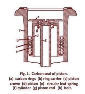 (The magazine illustrations weren’t sometimes too clear. The magazine was almost 70 years old and it’s possible that British wartime rationing didn’t help as regards paper and ink quality. The drawings have been either modified or replaced as possible. Absolute reliance on the images should not be taken as they are best interpretation. Ed.) Upon removal of the cylinder head, the carbon rings (a), as shown in Fig. 1, are slipped over the piston (d) together with the ring carriers (b). Circular leaf springs (e) serve to press the carbon rings lightly against the wall (f) of the cylinder. The piston crown is connected with the piston rod by means of the bolts (h). As these bolts exhibited fissures after short time in service, they were subsequently replaced by longer ones. The method employed for sealing the valve spindles is outlined in Fig. 2. Here it will be seen that the carbon bush (b) serves both as guide for the spindle (a) and as first stage gland, the steam pressure being throttled to a certain extent by the labyrinth-action of the grooves provided in the carbon bush. Sealing of this carbon bush against the valve body is effected at top and bottom of the bush by means of the elastic copper packings (c), the required degree of compression being exerted by the threaded gland (d). 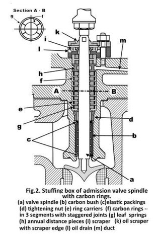 The stuffing box proper is constituted by the ring carriers (e)containing the carbon rings (f). Each of the latter is composed of three circular segments, the segments of adjacent rings being staggered by 60 deg. (Detailed section A-B in Fig. 2). The carbon segments are pressed against the valve spindle by means of the insular leaf springs (g). Furthermore, locating pins are provided to keep the carbon segments from rotating. In order to prevent the leakage of steam to atmosphere, distance piece (h) is inserted below the two topmost rings, this annular distance piece connecting with the back-pressure steam space by means of the duct (m). The two topmost carbon rings therefore act only as seals against the back pressure of the engine. In this way steam loss is kept to a minimum. The rings (i) and (k) act as oil wipers, with the leakage oil being led away through the opening (l). The mutual angular disposition of the six cranks of the engine crankshaft is indicated in Fig. 3. The connecting rods are forged and milled in order to keep their weight to a minimum. The big end bearings are made in cast steel halves, while the crosshead bearings are of the box type. The light metal crossheads have wrist pins of special bronze. The crank case is a single welded piece in order to avoid bolting the crank shaft bearings; the latter are bolted to pedestals enabling the withdrawal of the crankshaft to one side without lifting it. The cylindrical crosshead guides are made in halves and can be easily removed together with the crossheads through the openings provided in the engine casing. In the original engine the piston rods and certain other parts were made of stainless steel, but this precaution was later found to be unnecessary. 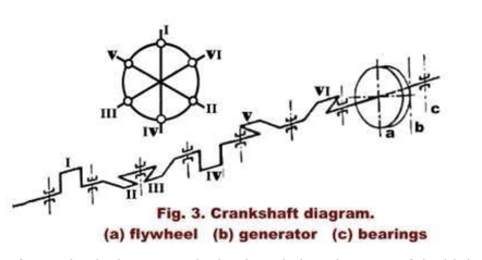 The employment of a mechanical governor had to be ruled out because of the high engine speed and the large controlling forces required, and a pressure oil governor system was therefore adopted, as shown in Fig. 4. The pressure oil pump as well as the gear type lubricating oil pump are driven from the engine shaft. Referring to Fig. 4 it will be seen that the small fly-ball governor (b) acts upon the pilot valve (c) of the slave cylinder (d). Valve control is effected in a novel manner, there being a cut-off control lay-shaft in addition to the main lay-shaft. The admission valves (e) are controlled by the cams (g) and the exhaust valves by the cams (h). The main lay-shaft revolves at constant speed, while the angular position of the cut-off layshaft relative to the main lay-shaft can be adjusted by shifting the pinion (i) by the movement of the piston of slave cylinder (c). Electrical remote engine speed control is provided. The engine is equipped with lubricating oil and pressure oil coolers, oil filters, and an emergency governor with oil hydraulic operation of the throttle valve. A manually operated pressure oil pump to set up the required oil pressure for starting is also provided. Provision for the absorption of thermal expansion is made at all vital points, including the steam piping. 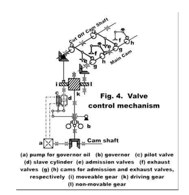 The steam supply line from the boiler was laid out with a minimum of bends, a distributing header being provided close to the cylinders. From observations made at points of the live steam connections close to the admission valves, it was found that there prevailed a weak steam oscillation of a frequency corresponding to the rotational speed of the engine. In addition to this, higher harmonics and a certain amount of non-harmonics were also found to prevail. The most suitable means for the suppression of these oscillations has not been found as yet. As the compression amounts to about two-thirds of the admission pressure, there also occurred a small amount of vibration of the admission valves, but this could be eliminated by changing the valve springs. Compared to a slow speed poppet-valve engine of equal power at 125 r.p.m., the present engine affords a saving in weight of some 60 per cent. At the end of August,1944, the engine had been in service for about 8,000 hours without showing any marked wear of the carbon rings. The amount of cylinder lubricating oil saved during this period amounts to more than 5,000 kg. The guaranteed specific steam consumption was 11.2 kg. per kW.-hr. (18.4 lbs. per h.p.-hr. - Ed.) with a tolerance of +5 per cent, with a load of 410 h.p. This compares with a measured consumption of 11.95 kg. per kW. hr.,(19.6 lbs. per h.p.-hr. – Ed.) that is, +6.7 per cent in excess of the guaranteed consumption. From diagrams taken at a later date, it was, however, found that two cylinders showed insufficient compression owing to faulty adjustment of the valve control. It is therefore confidently expected that after proper adjustment has been made the guaranteed steam rate will be met without tolerance. The indicator diagrams reproduced in Figs. 5 and 6 were taken with an electrical indicator. They clearly show the resonant oscillations occurring during the admission period. 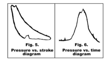 (A couple of notes seem worth mention. It mentions that the cylinder walls should be quite hard and as smooth as possible. This seems reasonable as graphite is soft and would wear away against an even mildly abrasive surface. Industrial hard chrome (not the stuff put on cars and motorcycles for the sake of being shiny) sounds like it might fit the bill, if polished. To be clear, this would be the kind of chrome plated onto injection molds to reduce wear … and other such heavy-duty work. Hopefully the article has been of interest. It would seem to follow that, if this approach worked on engine cylinders, it might also be valid for piston valves. It becomes more debatable for slide valves given the pressure applied to the sealing surfaces. After having slaved over a hot keyboard to put the article into a computer, and reworking some drawings, Tim Nye pointed out that that I had missed the fact that Josef Rais, one of the authors, had previously taken out patents on carbon piston rings and seal. The US patent, which is probably the most easily accessed, was applied for in March of 1934 (originally April 21, 1933 in Czechoslovakia) and was granted on April 4, 1939. It carries the title “Packing Ring for Sealing the Pistons and Piston Rods and was assigned to the Skoda Works in Pilsen, Prague, Czechoslovakia. I have to thank Tim for this observation, it brings the article into much clearer focus. Rais makes the case for his patent, as follows: “This invention relates to a new and improved type of packing ring for sealing the pistons and piston rods of reciprocating engines and machines using working cylinders and reciprocating pistons. The known constructions of engines and machines of this type suffer from the disadvantage that the packing members must of necessity be lubricated with some special lubricant supplied from without. This requirement results in a considerable increase in the cost of running, and expensive means are necessary for reducing the quantity of lubricating oiI to the minimum. In steam engines, the lubricating oil contaminates the exhaust steam, so that the latter cans not be used for certain purposes, since it contains excessively large quantities of oil. In the case of compressors, the lubricating oil can be caused to ignite. In consequence of the increased air temperature, thereby resulting in an explosion and hence the destruction of the entire machine. (When working with 5,000 psi air compressors, while in the Navy, we used special vegetable based oils for cylinder lubrication specifically to avoid these explosions. Ed.) Furthermore, the coolers are apt to become fouled by the lubricating oil, so that a special oil eliminating device becomes necessary. In the case of compressors in which a lubricant other than oil is employed, the pistons must be provided with soft packing means, for example cups, which are, however, comparatively short lived. In the case of refrigerating machines also, the lubrication with oil, glycerine, and other lubricants often gives rise to troublesome disturbances. Similar inconveniences due to the necessity for lubrication occur in the case of internal combustion engines also. The present invention overcomes these drawbacks by virtue of the arrangement that the packing members of the pistons or piston rods, or of both, consist of rings of carbon, graphite, or similar frictionless self-lubricating material, which rings are so resiliently mounted relatively to spring metallic supporting or holding means, that the necessary radial resiliency is provided without any independent lubrication whatever. These carbon rings are inserted in metal holding bushes, both the ring of self-lubricating matter's and also the resilient metal holding means being cut through by a single cut, for the purpose of enabling the entire packing member to be resilient radially. The packing ring according to the invention is rendered particularly well able to withstand the strains and stresses to which it is subjected by virtue of the arrangement that the ring consists of two coaxial independent rings loosely mounted one upon the other.” Rais notes: “In the hitherto known constructions of packing rings of carbon, graphite, or similar material the ring is either divided into a plurality of segments or else is rigidly connected to a metallic base. The first mentioned principle of construction does not ensure a perfect seal nor a uniform pressure of the packing ring against the co-operating surface, whereas with the second principle of construction the Independent stressing of the carbon packing ring is prevented, and in addition detrimental stresses are transmitted from the underlying base to the carbon ring whereby either the connection between the carbon ring and the metallic underlying base or else the carbon ring itself is damaged. These disadvantages are overcome by the present invention, by virtue of the arrangement that the metallic ring is loosely inserted in the carbon ring, with possible locking against lateral displacement. In accordance with the invention, the packing ring may for this purpose consist of two coaxial and independent rings loosely mounted one upon the other. These two rings are mounted one upon the other without any rigid interconnection whatever, with the result that the resilient action of the metallic ring is uniformly transmitted to the carbon packing ring. The sealing action of a packing ring constructed in accordance with the invention can be increased or reduced as required in the various cases of utilizing the rings in machines by choosing suitable metallic resilient material for the production of the resilient metallic ring. The seating surface between the two rings can be cylindrical; but may with advantage be provided with one or more grooves of any desired cone figuration for the purpose of preventing axial displacement. Packing rings constructed in this manner permit of radial movement of the ring performing the packing function. In this case, however, if the grooves be of dovetail or other shape, it is necessary to provide such connection between carbon ring and metallic ring with an amount of play which admits of displacement within limits permitting of perfectly uniform resilience of the packing ring. The resilient packing ring according to the invention is cut through in a normal manner at one point on its periphery, the cut in the packing ring and that in the metallic ring but either coincident or in offset relation to each other.” The following illustrations are all derived from the patent, while the abbreviations in the table replace the number designations used to describe patent features (on the theory that it might be easier to remember MR stands for “metallic ring” rather than the number 13, or whatever). 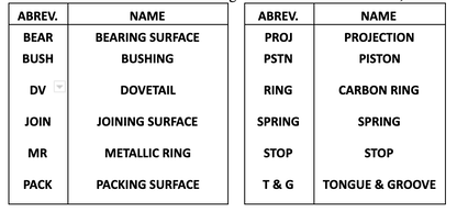 Figure1 shows three rings installed in the piston while Fig. 2 describes the rings themselves. 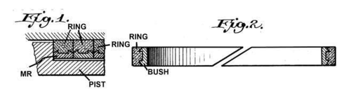 Figures 3 through 8 show a number of variations on the piston ring, these differing in the manner used to locate the carbon ring inside the metal ring; with Fig. 3 having no mechanical retention whatsoever other than contact with adjoining rings or piston grooves. 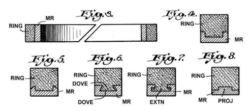 Figures 9 and 10 consist of packing assemblies holding multiple carbon rings. 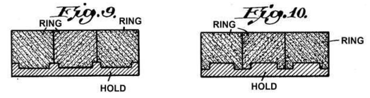 Figures 11 through 13 show pistons built up in segments, which serve to entrap the packing elements. The bushings are either a springy retainer or are backed by leaf or helical springs. The stops distribute the spring load against the bearing surface after the carbon rings have reached the worn in state. Thus, the springs are actually a temporary expedient used to break in the packing element. 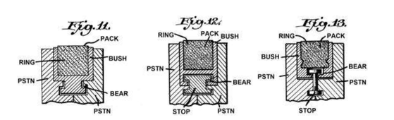 Figs. 14, 15, 17 and 18 also show sections of modified forms of packing rings inlaid in the material of the shell of the piston. Fig. 15 is a plan view of Fig. 14, and Fig. 18 a plan view of Fig. 17. In both instances, the split halves of the bushings connect with a tongue and groove to provide tighter joints. 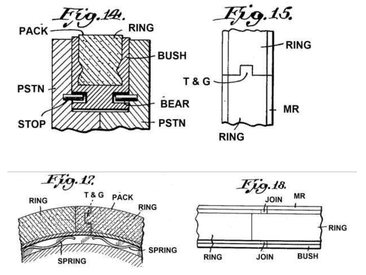 Generally speaking, the above embodiments are used with split, built-up pistons. Figures 21 and 22 are designed to be installed into the groove of a solid piston. Leaf springs underneath force the carbon ring against the cylinder walls while the stops are pins driven into holes drilled into the piston grooves from either the top or bottom of the piston. The rings are made in halves and use tongue and groove joints to promote tightness. 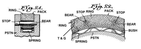 Rais noted: “In accordance with the invention the packing ring may be constructed in such a manner that its resiliency in a radial sense is effected by metallic means provided beneath the ring.” This implies that he understood the metallic ring would supply the resiliency required to hold the carbon packing in contact with the sealing surface but did not rule out the natural resiliency of the graphite itself. Today, we might have a greater range of options. At least two companies manufacture carbon materials engineered with an array of properties. Graphitar products are manufactured by US Graphite in Saginaw, Michigan while Superior Graphite is headquartered in Chicago, Illinois. Superior Graphite has been in business since 1917 while US Graphite was a spinoff of the Wickes lumber business and was founded in 1895 to exploit then-recent graphite discoveries in Mexico. The following comes from the Superior Graphite website found at: http://graphitescarbons.superiorgraphite.com/Asset/RGC-Brochure.pdf 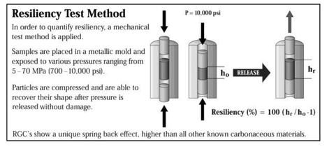 (RGC stands for ‘Resilient Graphitic Composites’, Ed.) 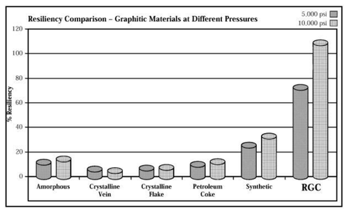 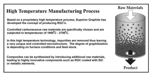 US Graphite sells what appear to be similar engineered graphite products under the tradename ‘Graphitar’. There are a wide variety of Graphitar products with specific properties for a range of applications. These can be molded directly to shape, or machined, whichever is advantageous. The company website shows their products being used for mechanical seal faces, as bearings (dry and water lubricated) and to form vanes, rotors and pump pistons. Perhaps some of these engineered carbon products have a place in modern steam automobile engineering.
Data sheets for their various products include such data as resilience, strength, hardness, porosity, temperature limits, PV factors, oxidation and chemical resistance can be found at: http://www.usggledco.co.uk/Resources. The Bulletin staff would enjoy any experiences you may share regarding carbonaceous materials as applied to steam engines. 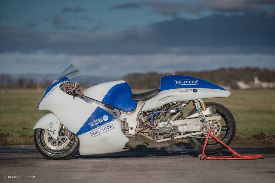 The Development of a Steam Powered Motorcycle PART ONE The following article covers the basic design philosophy for an attempt at the land speed record for a steam powered motorcycle and perhaps the outright record for any steam powered vehicle. As a starting place for a steam powered land speed record, a motorcycle is a terrible idea. The restricted space envelope and poor aero-dynamic characteristics make it the worst possible concept. However, not to be daunted that is what we chose. The decisive factor was because we had this small Bower and Bell engine, which was an Abner Doble inspired design, it is too small for a car, but deserved to be used in something. Our love of motorbikes and the idea of a steam powered motorbike is more appealing to us than the ultimate record itself, we have used a Suzuki Hayabusa as the donor vehicle. The basic formula pertaining to drag is: Drag = Cd x (1/2 x density of air x velocity2 x Area), where Cd is the co-efficient of drag and Area is the projected frontal area. As we can see, drag increases by the squared function of speed. The two most important factors that we can control in design space is frontal area and the Cd. A motorbike has a relatively small frontal area, which is good,. However, even fully faired racing motorbikes struggle to achieve better than a Cd of 0.6. This compares to 0.3 for a modern road car, a Streamliner can have Cd as low as 0.12.From the RSR Bonneville Aero-Horsepower & Drag Loss Calculator: available online at: - https://www.rbracing-rsr.com/aerohpcalc.html Coefficient of Drag: Street, faired motorcycles are notoriously inefficient aero-devices with Coefficient of Drag (Cd) figures in the 0.6 range. For example, a Suzuki Hayabusa has a Cd of .561 whereas a Kawasaki ZX-12 has a Cd of 0.603. Modern cars often have paid close attention to aerodynamics and may have Cd figures of 0.3. Streamliners may have Cd figures of under 0.2, perhaps as low as 0.15 or in some cases figures of 0.10 have been achieved. Frontal Area: Reducing frontal area is key to going fast as the horsepower requirements go up exponentially as you push that "barn door" through the air. You'll need a close approximation of your vehicle's frontal area in square feet to make this calculator entry. A Suzuki Hayabusa has a frontal area of 6.01 square feet. A Kawasaki ZX-12 has a frontal area of 6.09 square feet. Some streamliners like the Lambky Vincent have only 4 square feet frontal area. Vehicle Weight: On shorter courses with asphalt surfaces and good traction weight is more of an issue than it is at Bonneville, where weight can aid traction on the slippery salt surface. Short courses are more of a drag race and accelerating extra mass is not a good idea. At Bonneville the big dogs will be on the long course with over six miles of salt with the clocks at the 2, 4, and 6-mile markers, so weight is not nearly as much of an issue. 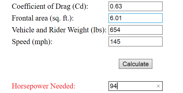 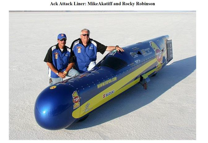 Figure 1: An example of a record setting Streamliner at Bonneville 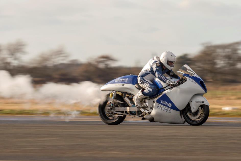 Figure 2: At Elvington airfield UK setting 80mph run Basic Design. The engine was chosen due to availability and suitability (mainly size). In some respects this is not an ideal engine for the task. However, it was suitable and most importantly available! The engine in question is a double acting Bower and Bell V twin, a modest 1.25 in diameter high pressure cylinder and 2.5-inch diameter Low pressure cylinder, the stroke is 1.5 inches with a fixed 50% cut-off. Various figures are bandied around for its power, approximately 30hp at 3000rpm with 1500psi has been quoted. One owner from Scotland who carried out trials with a Dynamometer, has stated that he achieved 22hp at 840psi and a constant 1890rpm. Calculations carried out indicate correlation with the reported test results from Scotland. Interestingly using the same calculator with the quoted 1500psi and 3000rpm show around 32Hp from the Hp cylinder only. Alternatively calculating for both cylinders (including subtracting the negative work from the HP cylinder on its exhaust stroke) shows ~29HP as a single acting engine, if allowing for double acting, then power is ~58Hp. We intend to push it as far as we can, using the spreadsheet I have created using 840psi, 1890rpm it predicts 20.8hp compared to the 22hp reported. At 3600 rpm, 2000psi and 900F, it predicts 94hp. I’m somewhat sceptical that the engine will produce this or indeed hold together. However, that is what we intend to trial on the Dyno. As far as the spreadsheet goes, it is quite complex and is not a simple pro-rata affair. When data from other verified engines is entered, it predicts values commensurate with those reported. So, until proven otherwise, we have to believe the numbers at this stage! The water and fuel usage are calculated at 743lb/hr of water and 8.96US-Gallon/hr of Kerosene at full power. The bike carries 53lb of water, enough for about 4 minutes running at full power. However, to go from a standing start to one mile only takes around 30 seconds, so this is ample for the purpose. Fuel has rather more in reserve, as fuel is consumed even when water isn’t, to maintain temperature and pressure, for example on the paddock stand before a run. In theory the engine should hold together, as it has been proven to be quite happy at 3600rpm. The small (0.75 inch) crank throw, means that piston velocity is no higher than other steam engines with longer throws and maximum torque is generated at low rpm. Therefore, if it doesn’t break at the start up, then there is no reason to believe it will fail at the high revs. However, since engine failure must be quite a credible possibility, the engine output shaft has been fitted with a bespoke free wheeling hub such that if the engine locks up, the rear wheel will remain free to rotate. See Figure 3 below 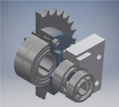 Figure 3:Sprag clutch freewheeling hub with water pump output shaft. A mechanical water pump is fitted to the end of the free-wheeling hub output shaft. This delivers all of the water necessary. The capacity of the water pump is approximately 200% of theoretical demand, ensuring the ability to rapidly increase the water level within the steam generator if steam temperature is too high. The water pump is driven by an eccentric, which can be changed to provide different water delivery, should testing reveal changes are required. Water must be added to the steam generator at start up by external means, as no electrical or hand pump is provided on the bike. We have chosen to run the steam generator at between 900 and 950 Fahrenheit. The steam lubricating oil limit is 1000F. This increase in temperature results in reduced water consumption for a given power. Abner Doble typically used 850lb/hr at 850F as the requirement for a 100Hp engine. This aligns with the water consumption predicted by my spreadsheet. Steam Generator The steam generator has been designed to output sufficient steam for 96Hp, which is 750lb/hr at 950F. The basis for all fluid velocities and required surface area has been calculated from the work of Abner Doble, including the required combustion volume. The steam generator has ~430 feet of 8mm OD tube for the water coils, 180 feet of 12mm OD tube for the steaming coils, 30 feet of ½ OD tube for the Normaliser and 30 feet of ½ OD tube for the super heater. The water and steaming coils are carbon steel for improved heat transfer properties. This minimizes the required tubing and the Normaliser and Superheater coils are 316L stainless steel to withstand the higher temperatures. The total weight of tubing is 120lbs and the internal volume is 0.3 cubic feet. If one considers that the required output of 727lb/hr equals 12lb/min and the internal volume is sufficient for ~9.5lb of water/steam, then simplistically the approximate time that a molecule of water entering at the inlet to the generator takes to subsequently exit the generator at 950F is (9.5/12) *60 = 47.5 seconds. At full power the velocity in the water tubes is 9ft/ sec, in the steaming coils 50ft/sec and in the superheater 75 ft/sec. Therefore, notionally the water spends 48 seconds in the water coils, 3.6 seconds in the steaming coils and 0.8 of a second in the superheater. This might seem incredibly fast. However, comparing to Abner Doble’s design for a 100Hp generator producing 850lb/hr of steam at 1000psi, (steam at this temperature and pressure has a density of ~1.39lb/cubic foot). Producing 850/3600 = 0.236lb/sec. The super heater and normaliser coils are 3/4inch OD, 9/16inch ID and 39 feet total length. The cross-sectional area is therefore 0.2485inch2. The volume in the superheater is (39*0.2485/144) = 0.0673feet3, so contains 1.39*0.0673 = 0.0936lbs of steam. Therefore, to produce 0.235lb per second, requires the superheater to be emptied 0.235/0.0936 = 2.5 times per second, 2.5 times 39 is 98 feet per second velocity! 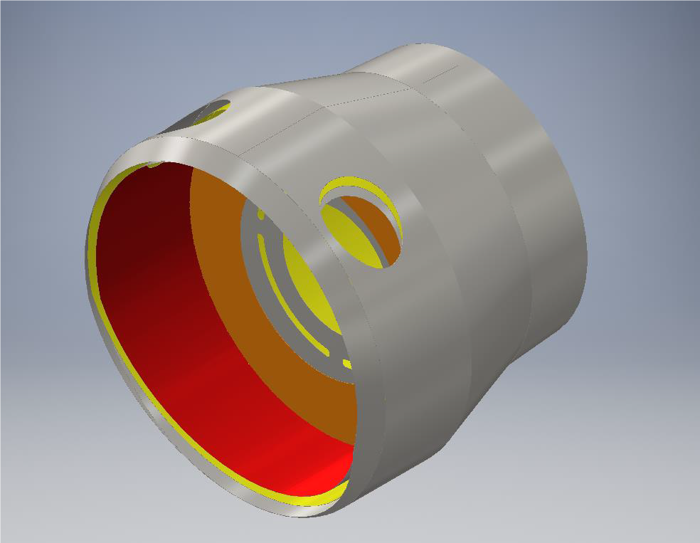 Figure 4: Steam generator casing For the generator controls we have a temperature sensor (referred to as TC1) at the end of the steaming coils, a Normaliser inlet at the start of the Normaliser coils for adding water to the top coils, should steam temperature be excessive. This is sized to allow for approximately 10% of feed water, followed by a pressure sensor (P1) and second temperature sensor (TC2) at the outlet from the generator. This follows broadly other successful control systems for monotube steam generators 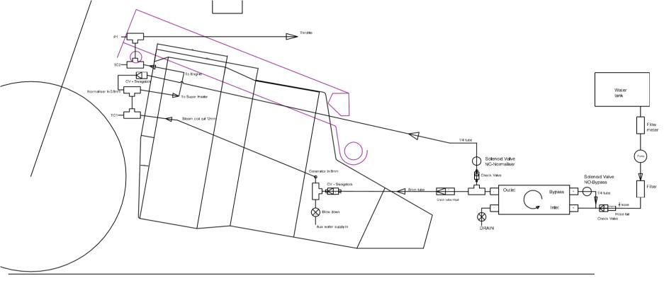 Figure 5: Schematic of plumbing At the steam chest on the engine, a third temperature sensor (TC3) and second pressure sensor (P2) is located. This is important for the generator control system as will be described later. The regulator is a fly by wire control. A suitably rated regulating stem needle valve is located between the generator and the bike engine. The twist grip throttle is in fact a potentiometer. This electrical signal is used via a controller to move a stepper motor, which actuates the valve. The controller is within a military spec case for protection and has its own Uninterruptable Power Supply (UPS). This consists of a stack of Super Capacitors, which charge as soon as power is connected to the bike. Should input signal or external power be lost, the controller automatically runs a valve close procedure, using the stored electrical energy within the Super Caps. The control and power cables to and from the stepper motor and control box, are run within an armoured sheath. As a back up to the regulator, a second valve is positioned upstream and is actuated by a hydraulic cylinder from the clutch lever. This ensures that the rider can manually shut of steam to the engine. However, once used, this valve can only be reset after all pressure is drained from the generator. The water pump has a pulsation damper fitted at the outlet and a relief valve set at 2300psi to protect the pump and damper. Between the water inlet to the generator and the water pump, are two check valves. Closest to the pump is a poppet check valve with polymeric seal. At the generator inlet is a metal seat lift check valve, rated for 3280psi at 900F. Immediately after the metal seat check valve is a relief valve set at 2500psi. Should the pressure exceed this within the generator, this will ensure the liquid content of the generator is immediately released, (albeit flashing of to steam in the process), therefore collapsing the pressure. The lower set water water-pump relief ensures that the mechanical pump can’t deliver water should the generator pressure be high enough to lift the generator relief. The main electrical power for the bike is provided by 3 in number 24v Lithium batteries each containing ~10Ahr. They can sustain a continuous discharge of 15 amps (each) with 70amps peak. At full load the fuel pump draws 8 amps, the air fan 20 amps, the control system 6 amps and the electrical boost pump (water suction delivery for mechanical pump) 3 amps. Total 37 amps. Burner The burner consists of a single flame tube containing an atomizing oil nozzle by DELAVAN. This is a Variflow nozzle that allows for modulation. 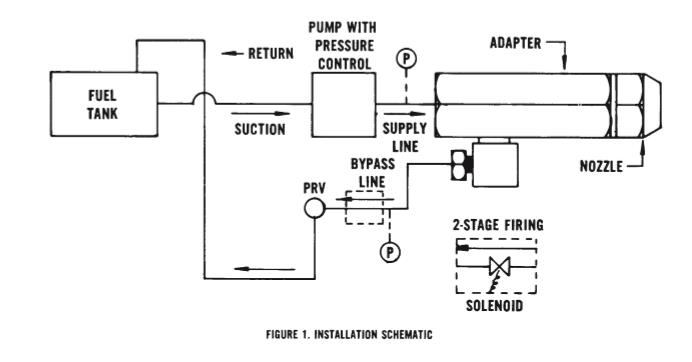 Figure 6: Burner schematic This system allows for a minimum firing rate of just over 1gal/hr, up-to a maximum of 9.9gal/hr> This is achieved via three control modes. At constant pressure (100psi) the bypass line is controlled via pulse width modulation (PWM) of a solenoid controlled PRV. This allows (with the nozzle we have selected) a firing range from 1.2 to 6 gal/hr. With the bypass line fully closed, fuel pressure can be increased (max 300psi) to give up-to 9.9gal/hr. This is achieved through PWM control of the fuel pump motor. Air is supplied via an Electric Ducted fan intended for radio-controlled aircraft. Again, through PWM, the air supply can be matched to the fuel delivery to give the correct air fuel ratio. 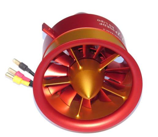 Figure 7: 3 phase 24V EDF Control System It should be stated at this point, that what has been described to date reflects the current status of the design. An earlier version of both the generator and control system have been physically trialled, and speeds of around 80mph achieved. This was very disappointing to ourselves, as we hoped to easily break the 100mph mark. However, subsequent investigations revealed that the generator was woefully under tubed, containing only enough tube for around 25hp, the burner could only deliver 3gal/hr. The piston rings were broken on the valve gear due to standing for a long time, such that the engine was severely compromised. With a fixed cut-off engine, it is extremely important that the generator can provide as much steam as is demanded, without the ability to reduce cut-off there is no ability to reduce steam consumption if pressure and temperature are low, this creates a vicious circle when it comes to monotube steam generators. The control and protection philosophy are as follows. The normal operational envelope is controlled via a small computer, vis a raspberry Pi, controlling fuel, water and air. 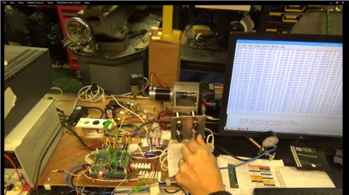 Figure 8: Test bed for Raspberry Pi control system If the system strays outside of the normal operational envelope, there exists a hard-wired relay-based protection system. This utilises industrial process temperature and pressure controllers, which hold the power relays made. Should protection limits be exceeded, power is removed from the relays, effectively shutting down the burner etc, regardless of what demand signals may be being sent by the control system. Should this hard-wired electrical system fail, then beyond this, we have physical mechanical pressure reliefs and an emergency steam shut of valve hydraulically operated via the clutch lever. A thumb kill-switch and a kill-cord are also provided, which have the effect of removing all power (shutting fuel solenoids etc). As previously described the regulator will then automatically shut upon loss of signal or external power. 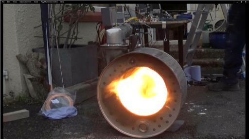 Figure 9: Dummy combustion chamber to trial control system Demand for fuel is calculated from the steam chest conditions. i.e. temperature and pressure within the steam chest determine steam density and thus the heat content of the volume of steam used. Steam density is calculated in real time by the PLC using a five-order polynomial equation I developed from steam tables. It is sufficiently accurate across the permissible operating range of pressures and temperatures that we are using. Swept volume, inlet cut off and rpm are then used to calculate mass flow rate of steam. 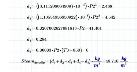 Figure 10: Formula for steam density used by PLC  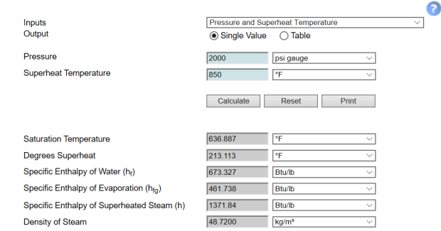 Figure 11: Actual values for steam at 850F and 2000psi from https://beta.spiraxsarco.com/resources-and-design-tools/steam-tables/superheated-steam-region#artical-top Steam Mass flow rate = Swept volume x cut off x rpm x steam density. Since inlet flow conditions and the effectiveness of the piston and valve rings will affect the real value, a multiplying factor is utilised. This can only be determined for a given engine via experiment and we have assigned this the notation leakage factor. From the pressure and temperature of the steam in the steam chest, the specific heat content can be calculated. Firstly, the saturated steam temperature is calculated using again a formula developed by ourselves, 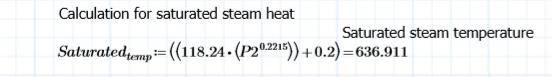 Figure 12: Formula for calculating Saturated steam temperature Using this the specific heat content of the saturated steam was derived initially using formula developed from the IAPWS Industrial Formulation 1997. Page 10 of 14 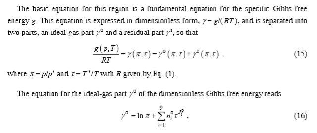 Figure 13: IAPWS Industrial Formulation 1997 for region 2. However, we have found that suitably accurate results for our region of operation can be achieved through the use of the following formula developed by ourselves. 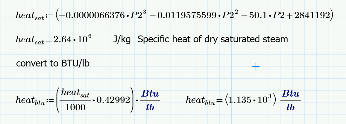 Figure 14: Formula for calculating specific heat of dry saturated steam Then the degrees of superheat above the saturation temperature are used to calculate the specific heat content due to superheat using a fourth equation developed. The sum of these values, is the total specific heat content of the steam being used by the engine. 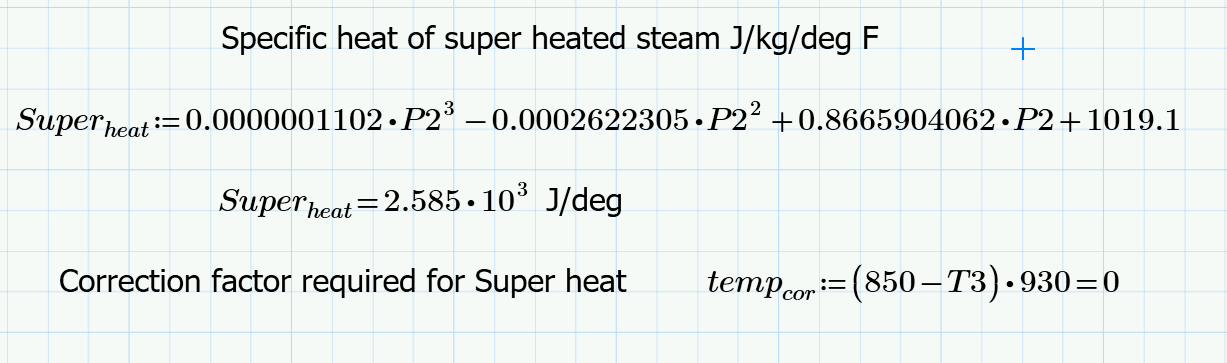 Figure 15: Formula for heat content due to superheat 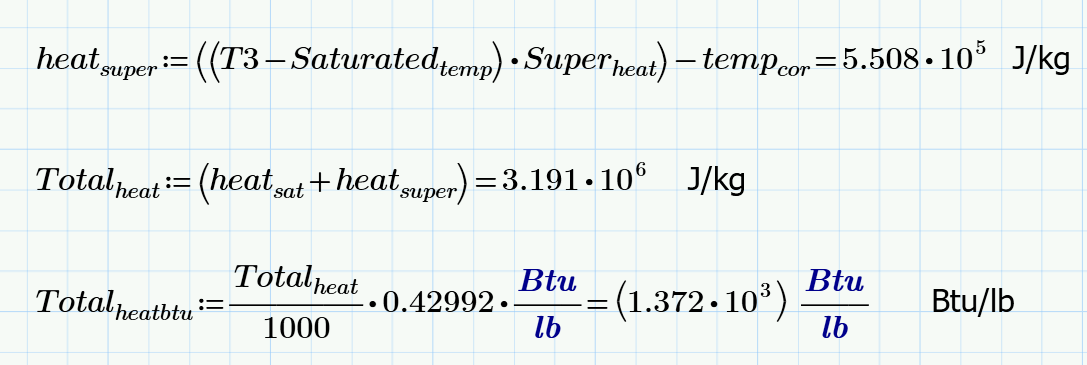 Figure 16: Formula that calculates the heat content of steam within the steam chest So the formula calculates the heat content of steam at 850F and 2000psi as 2.64x10⁶ + 5.508x10⁵ which equals 3.191x10⁶ J/kg or 1372 Btu/lb, this compares to 1371.84Btu/lb from the SpiraxSarco web site, an error of 0.16Btu/lb or 0.01%. The error increases to a maximum of around 1.5%, at 750F and 800psi. Provided temperature is maintained at above 800F the error across the conceivable pressure range in the steam chest is <1%, the error is largely associated with the Superheat term hence the correction factor. The PLC using the above formulas calculates the specific heat content of the superheated steam several times a second. The previously calculated steam density and swept volume is used to calculate the amount of steam being removed. 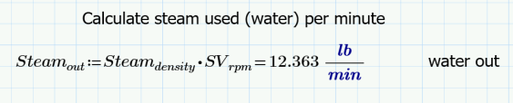 Then the heat removed from the generator is simply the mass flow rate x the heat content. 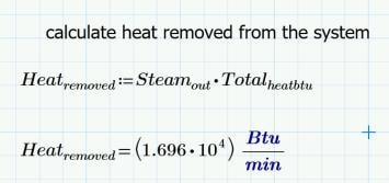 The generator efficiency is estimated from the relationship between mass flow rate/ heating surface area, the generator has been sized to achieve ~80% efficiency at full power. Since we now have a value for heat removed in BTU/hr the fuel demand is simply calculated from: 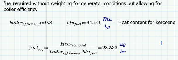 approximations within this approach, will be such that equilibrium is unlikely to be exactly achieved, as such temperature and pressure will rise or fall during operation in proportion to the errors within the calculations. There are various permutations. However, in simplistic terms (for the sake of this article) there are four basic scenarios, temperature to low or too high, and pressure too low or too high. 1. If temperature is low but pressure is good, then there is excess water in the generator, i.e. the water to saturated steam transition is too high up the coils. The remedy is to reduce feed water input. 2. If temperature is too high but pressure is good, then there is excessive heat and insufficient water. The remedy is to reduce burner input, and increase feed water (a normaliser can be used to control excess temperature. However, additional feed water must also be added at the bottom end to remedy the situation.) 3. If pressure is low but temperature is good, then again there is insufficient water in the coils. The remedy is to increase feed water and heat together. 4. If pressure is high but temperature is good, then there is too much water in the coils. However, both water and fuel must be reduced together. Formula for temperature and pressure correction factors have been created. These are used to bias the fuel demand and water delivery. Therefore, the initial fuel and water demand, which was calculated from heat/ steam being removed, is either increased or reduced according to the conditions in the steam generator relative to the operating set point. Clearly if either the boiler efficiency or the steam usage is significantly out, then the system will find equilibrium away from the desired set point. Therefore, trim pots are provided on the control interface to allow the boiler efficiency and or the leakage factor to be adjusted to bring the convergence in line with the operating point. An error in efficiency would result in issues related to heat input, errors in steam usage would result in issues with feed water rate. If steam usage was underestimated, then we will see an increase in temperature with a falling pressure. This is because there is a reducing water level in the generator. Therefore, the leakage factor must be increased. Should pressure be high and temperature low, then steam usage is overestimated and leakage factor should be reduced. Note the reduction in calculated steam removal has the effect of reducing both feed water and heat input proportionately. Therefore, pressure should reduce. However, temperature will be maintained via the reduced water level within the coils despite the proportional reduction in heat input. Should boiler efficiency be underestimated then we will see over temperature and over pressure. In this case boiler efficiency factor should be increased, this will reduce the fuel delivery. Should temperature and pressure be low, then boiler efficiency has been over estimated and the boiler efficiency factor should be reduced, thus increasing fuel delivery. So leakage factor increases or decreases feed water and fuel in proportion Boiler efficiency either increases or decreases burner input alone. There are three control modes:
Minimum Burn: At its lowest fuel pressure setting and with the return line fully open, the burner delivers approx. 1.2gal/hr. In this setting the burner cuts in and out at the operational point for pressure and or temperature, the fan continues to run at low speed to prevent a damaging heat soak, which could otherwise occur. The system stays in minimum burn, whilst demand is less than the minimum burn value (1.2gal/hr). Speeds in excess of 30mph will be required before demand exceeds minimum burn. PRV control: Once demand for fuel exceeds minimum burn mode, the system automatically switches to PRV control. Now the system varies the PRV position in the nozzle return line to match fuel delivery to demand. As the demand increases, the PRV progressively closes. The return flow meter is used to calculate fuel delivery. However, as the PRV approaches fully closed, the low flow starts to make the flow meter readings unreliable. As such, an algorithm is used to calculate return flow from PRV position at the final stages of closure. Unlike in minimum burn mode, the system modulates around the desired operating point. As previously described the fuel demand and water is modified based on generator conditions. Therefore, if pressure exceeds the operating point, this results in a reduction in fuel and feed water. The reduction progressively increases the further from the operating point the system gets. If this results in reducing steam temperature, then the feed water will be cut back further still. If the steam temperature actually rises due to the reduced feed water, then feed water is increased. Should the control system fail to keep the pressure and or temperature within the upper operating band around the set point, the system will drop into minimum burn mode. Once conditions return to within the operating band, the burner will ramp back up to the required demand again. Should, however, even minimum burn mode not prevent further pressure and or temperature rise, then upon reaching the safety limit the burner and feed water will fully shut down. Speed Control mode: Once fuel demand exceeds PRV mode, the return line valve and PRV are fully shut. Now fuel delivery is varied by increasing fuel pump speed. This has the effect of increasing fuel pressure in the fuel rail. Fuel pressure can be varied from 100 – 300 psi and at 300psi this gives 9.9g/hr. Modulation (including shut down) is as described for PRV control mode. Feed Water control The water pump is driven from the output shaft of the engine via the free-wheeling hub Therefore, even when coasting, the water pump is driven via the back wheel. However, no feed water is available when stationary. The outlet from the feed water pump has a recirculation line back to the inlet port of the pump via a solenoid valve. When this valve is open, no water is delivered to the generator. It is a simple task for the PLC to modulate the solenoid valve to control the proportion of water delivered. In addition, an offtake from the pump delivery goes to a second solenoid valve and from thence to the normaliser. Should the stem outlet temperature be too high, then the normaliser solenoid valve opens and allows cold water to injected to the top coils of the generator. The feed water entering at the bottom has an increased pressure compared to the steam leaving the generator at the top, due to the pressure drop related to velocity within the generator. As such the pressure delta increases with demand and so the fixed orifice in the normaliser nozzle has been sized to deliver approximately 10% of the feed water rate for any given speed and demand. The normalizer nozzle should consist of an orifice followed by approximately 3 inches of shroud within the steam main. This shroud is heated by the superheated steam. The water spray entering the shroud (via the orifice) is heated and turned to wet steam within the shroud before it mixes with the main steam flow, ensuring good mixing and efficient heat transfer between the gaseous fluids. If water is merely injected straight into the super heater coil, then the water droplets bead like water dropped on a hot plate and the effectiveness of the system is much reduced, (remember at full demand the velocity in the superheater is >75ft/sec), with a mix of wet and superheated steam leaving the generator outlet. The water pump is fixed displacement, thus the feed water rate is calculated from engine rpm and validated by a flow meter within the suction line to the pump. A non-return valve on the pump inlet ensures that when in bypass mode, the internal pressure in the pump is largely maintained and not just lost back to the water tank. An electric boost pump ensures that pump inlet conditions are maintained to prevent cavitation. Part two will follow after further updates to design and testing. Pat Farrell explaining how he balanced his 30 HP Stanley steam car engine. reprinted from SACA FORUM. Re: Balancing an old steam engine I added additional counterweights to our 30 HP Stanley engines' crankshafts. Before the added weights, the Stanley engines started bouncing at about 47 M.P.H. Just minutes ago, I just blew down our 1911 Stanley model 85 7 passenger 30 HP touring after a 25 mile demonstration ride. I was giving some of my classmates (class of 1963) a thrilling ride at 70 MPH and there wasn't a bit of bounce anywhere coming from the engine. Smooth as silk! The Stanley still had more throttle left to use. The 30 HP Stanley car is unbelievable! The added counter weights made it just that much better. The counterweights that I added to our 30 HP Stanley engine were almost the same size as the counterweights that the engine throws already had on it. I do not know their exact weight. The were crafted by REMPCO in Cadillac, Michigan by Gilbert "Red" Hall. Phone number 1-800-736-0108 If one has a 30 HP Stanley and he is not using these counterweights as of yet, then they have not experienced the true smoother higher speed potential of their Stanley. Our model 85 is geared 50 to 60. Almost one to one. The tires are 36" in over all diameter. At 70 MPH, the Stanley engine is smoothly just loafing along. Our 1911 Stanley model 85 7 passenger, 30 HP is old technology that they already had by 1911 and about 50 years of research in it to make it the most advanced form of transportation of its time. By updating in the proper areas, like engine balancing, modern metals, better brake lining, safety glass, better tires, so on and so on, we presently have one of the most advance forms of steam transportation in this modern era. Our model 85 has never disappointed me in its performance or reliability. I drive with modern traffic. Its handling is on par with many modern vehicles. My only short comings are that about every 50 miles I have to look for water, and I have to be cautious with its two wheel brakes. My pride is that this Stanley is that it is all scratch built with scrounged up parts by me. I tried to make it historically accurate too. People who scratch build their modern steam cars are unfortunate in that they often are trying to re invent the wheel again by using previous failed inventions. If the modern steam car builders would comb the back issues of our Steam Car Bulletins, they could learn a lot from the failed past ideas used with steam cars. Oh yes. I have had a lot or reworked parts through the years too. Perfection eventually arrives.  Image above is a conversion done in England by Basil Craske similar to Pats idea.
I was sitting with my mom and dad talking about my mom’s side of the family and what I had recently learned about them. My Dad said, “Why don’t you try and find some information on the Ashton side of the family?”. “Sure”, I replied. I immediately found Ashton Valve online. Most of the references were links to Ashton items that had sold on Ebay. It wasn’t long before I had photographs of long deceased relatives that my Dad had never seen before. My scrapbooks soon filled with hundreds of old advertisements and articles I had downloaded from turn of the century steam trade journals. The book shelves at my house started to fill with old gauges and other artifacts related to Ashton Valve purchased on Ebay. One of my friends who happens to be a steam enthusiast suggested I visit the annual “Steam Up” at the New England Wireless and Steam Museum in Rhode Island. I contacted the people running the museum and they loved my idea of having an Ashton Valve exhibit at the event. I honestly had my doubts that anyone would care about a largely forgotten company. I was wrong. Quite a few people asked me questions about the company and told their stories about working with steam. I had purchased a CD online of old Ashton Valve catalogs and the man who sold it to me surprised me by showing up at the show and giving me a safety valve from 1874, and a stock certificated dated 1877. That day in Rhode Island was very inspirational to me. Not long after that, the same friend who told me about the “Steam Up” mentioned a museum he had visited some years back that had sponsored a steam show he thought was excellent, and suggested I check out the museum sometime. It was the Charles River Museum of Industry and Innovation. A few emails and a couple of visits later and here I am, talking about Ashton Valve and looking forward to the exhibit that will be here sometime this year. 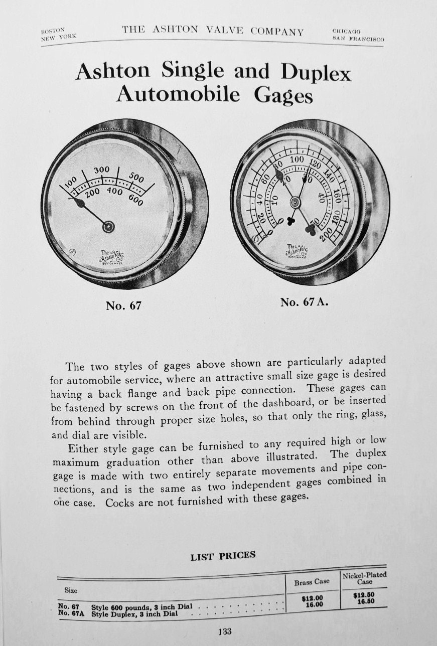 I’ll be talking about a company that lasted over 100 years, a company that started with 4 employees and a vision to try and make boilers safer. At their peak, they employed around 300 people and were known worldwide for their quality products used in locomotives, ships, and power houses. I would also like to think their products saved a few lives along the way, because boilers can be like bombs. Ashton Valves was born out of Henry Ashton’s desire to make boiler rooms a safer place to work. In the mid to late 1800’s people were dying at an alarming rate. In one year in the mid 1860’s more than 1,000 people died due to boiler explosions and even more were injured. In April of 1865 the paddle steamer “Sultana”, carrying Union prisoners back North from Confederate prison camps exploded, resulting in the loss of 1500 lives. Another explosion in July of 1894 at a lumber mill caused the death of 4 workers and did substantial damage to the mill. It was a horizontal tube type boiler and when the explosion occurred the pressure was probably about 500 psi. The boiler head was blown out and the rest of the shell left the boiler room and flew through the air for a distance of over 1200 feet. During it’s flight it passed through the mill and over several houses at a height of about 80 feet. The last 350 feet of it’s flight was through a dense and heavy woods where it cut off everything in it’s path including a tree which was 28 inches in diameter. The insurance company stated “the safety valve did not work.” It obviously wasn’t an Ashton Valve! 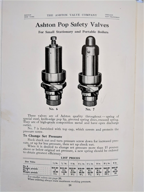 In May of 1894 many people living in the town of West Bay City were terrified by the explosion of a boiler in the local planning mill. Buildings in the area were badly shaken up and the sidewalks of buildings nearby were littered with the glass from broken windows. The mill itself was wrecked and the boiler blown into 4 pieces. The engineer was blown against a sewing machine, cutting his lungs and heart out. Brick was thrown for a quarter of a mile. The late engineer was known to have a habit of running boilers with low water, claiming it was more efficient. In the years between 1885 and 1895, there were an average of 200 boiler explosions a year. Between 1895 and 1905, there were 3216 boiler explosions in the United States, and average of one a day, resulting in 7600 deaths and countless injuries. As recently as 2017, a man in Revere Mass died while tinkering with a faulty boiler. The explosion blew out the basement windows and a door clean off the hinges. There is an old quote “Necessity is the Mother of Invention”. The time was ripe for a major improvement. Time to introduce Henry Ashton. Henry was born in Norfolk, England in 1846. His basic schooling was supplemented by a course in mechanical and steam engineering. He arrived in Boston in 1869 with his wife Emma and a 2 year old son Alfred. He found work at the Hinckley Locomotive Works on Albany Street. He invented the lock up pop safety relief valve for steam engines in 1871 while working as the superintendent of refilling at the Eagle Sugar Refinery in Cambridge. He opened up shop at 138 Pearl Street with 3 other employees under the name Ashton’s Lock Safety Valve Co. He was burned out by the Great Boston Fire of 1872. 67 acres of what is now known as the business district was destroyed with the loss of 767 buildings. Wooden buildings, high winds, and a shortage of horses to pull firefighting equipment all contributed to the destruction. 1873 finds the company at 9 Rowes Wharf by the waterfront. In 1874 they moved to 261 Purchase St where they stayed for 4 years. The Cathedral File in 1878 burned the company out from their location at 93 Federal Street. Finally in 1879 they were able to attain some stability when the company moved to 271 Franklin St. They were at that location for 27 years. Another fire hit them in 1892, but the damage was minimal. The building was 4 floors to handle a business that had been growing rapidly since the introduction of the pop safety valve. In 1900, a fifth floor was added to keep up with the demand. They were always busy. In 1885, the Railway Purchasing Agent trade journal quoted the company as stating:” Ashton Valve has not discharged a man on account of any falling off in orders, nor run less than 10 hours a day during the last 4 years. The works are now running overtime in some departments”. 1892 was an important year for the company as they purchased the plant, patents, materials, and business of the Boston Steam Gage Company. As their trade journal release stated: “The reputation gained by nearly 20 years’ experience in the manufacture of safety valves and the widely recognized quality of the products of the Ashton Valve Company will be the only guarantee needed for the unsurpassed quality of the goods we shall put upon the market”. I find it surprising that it took them 21 years to get into the manufacture of gauges as they are the perfect complement to the other products they produced. And it wouldn’t be long before Ashton Gauges were as well known to the industry as the safety valves. History has shown that the gauges are what Ashton Valve is best known for today. at least on Ebay, where they can sell for substantial amounts of money. There was one listed a couple of months ago for $1700 dollars. They are works of art and quite popular with collectors and steam punk enthusiasts. 1895 was notable for the death of Henry Ashton, the company’s founder. Most of his responsibilities would be taken over by his son Albert, who had attended MIT, and would be an important figure in the daily operations of the company for the next 27 years. In the years between 1895 and 1922 the company produced 440,828 pressure gauges, the peak years being between 1915 and 1920. 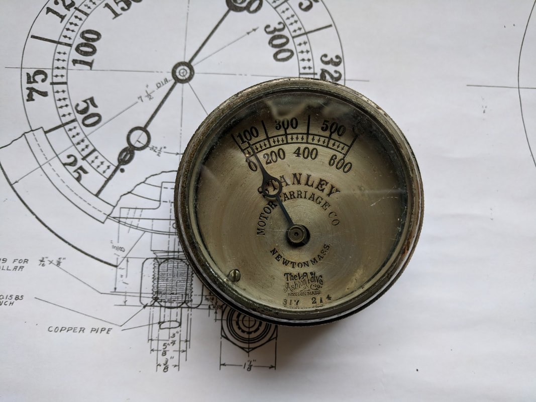 Trade shows, exhibitions, and conventions have always been an important part of any sales organization. They are essential opportunities to acquire new accounts, enjoy old customers, and check out the competition. These shows, as well as the many advertisements in trade journals, and the salesmen and distributors the company had all over the world kept the profile of the company high. The reputation of an Ashton valve or gauge as a long lasting top quality product was always heavily advertised. An ad in a 1921 trade journal read “Ashton products, unequaled for quality, efficiency, and durability, higher in first cost but cheapest in the end”. This was a time when you repaired things, you didn’t throw them away. The company had a full service gage repair service. A few of the shows the company attended are worth mentioning for the awards they returned home with. At a Boston show in 1874 the Mass Charitable Mechanics Association awarded them a silver medal for their pop safety valves. The Mass Charitable Mechanics Association was founded in 1795 with Paul Revere as its first president. It’s founding members first met to address the problem of runaway apprentices but soon evolved into a group committed to promoting the mechanical arts and raising money for member’s widows and families. It still exists today. Is anyone here involved with this group? Ashton Valves received a special premium award at the 1881 Cincinnati Industrial Exposition. In Chicago, they received another medal for pop safety valves at the 1893 World’s Fair. They crossed the Atlantic Ocean in 1900 for the Paris Exposition, bringing home 1 silver and 2 bronze medals. In 1904, at the St. Louis World’s Fair they received another silver medal for their display of safety valves and gauges. The late 1800’s were times of active growth in labor unions nationwide. Both the American Federation of Labor and the Boston Central Labor Union were gaining strength. After a walkout in 1895, Ashton Valve restored wages that had been reduced the previous year. In May of 1901, 53 machinists walked out of the Ashton Valve Company as part of a nationwide strike for shorter hours with no reduction in pay. In June the local strikers committee accepted the Ashton Valve proposal of a 9 hours day with no cut in wages. The workers of the time were working 6 ten hour days per week. In 1912 the Boston Molder’s Union #468 went on strike which resulted in a minimum wage of $3.50 per day! The Franklin St building they had occupied for 27 years couldn’t handle the business anymore and in 1907 they purchased land in Cambridge and built a 4 story 45,820 square foot building. Located at 161 First St, the building still stands today with the Ashton Valve name clearly visible on the granite lintel above the front entrance The Cambridge Historical Commission has some wonderful old newspaper articles on the building. It was built at a cost of $67,000. It was one of the first modern factories built in what now is the Kendall Square area of Cambridge. Built on reclaimed swamp land, the facility featured modern bathrooms and electricity throughout the entire building. The 4 floors included a fireproof store room for paper drawings, iron shop, foundry, and a special testing room in the back with it’s own boiler capable of creating steam up to 400 psi. It was obviously designed with the idea that a better environment would provide a more productive work force. In 1919, Albert Ashton introduced a course in modern production methods. The object of the course was to train the men in the principles of foreman-ship, to develop their qualities of leadership, and to give them a broader view of industry as a whole. Mr. Ashton, the president of the company, who is the originator and organizer of this movement, thought that course would help develop the men who took it as well as benefit the plant through increased efficiency created by better cooperation. He was also of the opinion employee relations would be strengthened because of the more careful handling of problems by the trained foreman. This was quite a contract to the Captain Bligh mentality used by many foreman and supervisors back then and even today. The business was still growing. The 1920’s and 1930’s were the peak years of the company’s influence. Their profit for the year 1916 was $182,234 or a little over 4 million in 2018 dollars. The year 1919 showed a profit of $214,178 or around 3.6 million in today’s dollars. Both numbers are pre-tax dollars. By 1922 there were around 250 employees. Ashton Valve had satellite offices in New York City, Chicago, London, San Francisco, Mexico City, Philadelphia, St. Louis, Cleveland, Genoa, Vienna, and Paris. The company helped form the Kendall Square Manufacturers Association and the Cambridge Industrial Association, which later became the Cambridge Chamber of Commerce. They were instrumental in starting a baseball and bowling league with other companies in the East Cambridge area. 1922 also saw the death of Albert Ashton, Henry’s son. He had been managing the company since Henry’s death in 1895. His brother Harry, who was the sales manager at the time, took over some of his administrative responsibilities. Business slowed in the 1940’s. Diesel locomotives, gas fuelled automobiles, and electricity as the main source of power all contributed to the decline in sales. According to the 1957 book “Atomic Power – It’s Significance to the Management of a Relief Valve”, “The Ashton Valve was a prime factor in the steam locomotive or railroad business, enjoying it’s best years in the late 1920’s and early 1930’s.  It’s contribution to the overall sales is one of diminishing proportions, another example to be anticipated when a company does not assume a responsible role in the design development and manufacture of competitive products for an ever-changing market.” Unfortunately for Ashton Valve, the company never ventured far from the production of their steam related products.
Ashton Valve merged with the Crosby Steam and Gage Company in 1948, sold the building to Nicholson & Co., an industrial adhesive manufacturer, and moved with Crosby into the old Winter Brothers Tap and Die building in Wrentham, MA. The Wrentham building was torn down in 2012, Crosby was purchased by Tyco and still operates out of a facility in Mansfield, MA. https://www.smokstak.com/forum/attachment.php?attachmentid=338041&d=1561734973 Rick Ashton Engine Block Unscrew elbows from the engine block and remove copper covering. It will expose oil soaked insulation which needs scraping off. I made a lifting hook mounted on the back to assist in moving the engine. Valve Cover The valve cover has a hole in it for the drip valve. The pipe used to help take the unit out of the car can be used as a fulcrum to wrench the cover off. It should be so oil soaked that it should screw off easily after you get it loose. One of the ears is missing which led me to modify a pipe to use against the remaining ear. It worked fine. When reassembling, the cover has packing in the top and needs removed and replaced with a strip of 1/8” packing. The cover was replaced with a new one Don Hoke had in stock in 2019. The valve surface should be smooth and not curved. Steam pushes the valve against the block and creates a seal. Gearbox The oil level in the gearbox should be about 1 1/2 “ from the bottom while in the car. Bearings and sliding/turning surfaces should have minimal of .001-.003" clearance. It is easy to over-tighten bolts, and looser is preferred over too tight, especially with cam and crank rods. Make copper shims to space everything appropriately. Crank gear The crank gear is significant as it has a larger gear welded on top of a smaller gear. This was a fairly common practice as road conditions improved over the years allowing higher speeds and welding an existing gear over the original one was a low cost option to replacing the entire crankshaft. 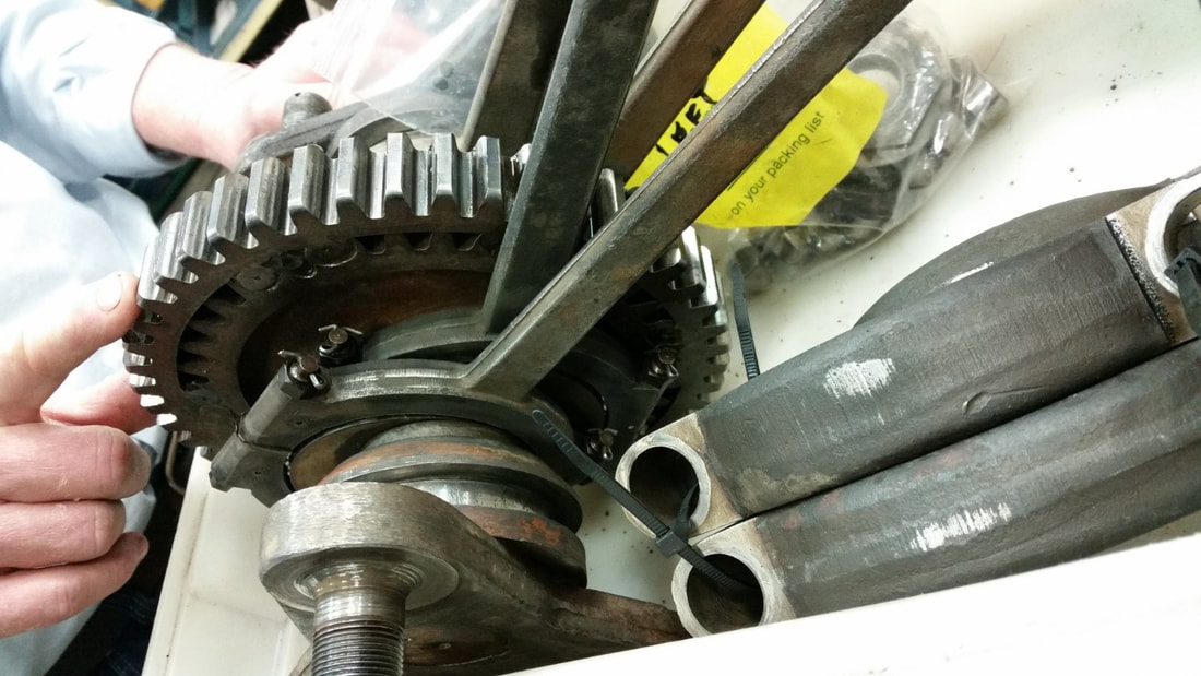 Rear Axle Differential Removing the rear wheel requires a special puller that fits in the hub. The complete axle with wheels weighs 394lbs. The main item to keep in mind is that play between the planetary gear and the spider needs to be as close to 0.001" as possible with less being more desirable than more. In the case of this car, there was so much play that the gears barely connected, resulting in catastrophic failure of all three spider gears as well as damage to the case. Adjustments to this play is achieved primarily through shims between the planetary gear and the inner bearing but also through shimming the cross members so that the case still fits over the assembly. The picture on the left shows a bit of the shims. on the right side, the housing is assembled over the differential, still allowing the axle to pivot. Axles Moving the planetary gears in ended up causing the axle to shift inwards on the rear end and the clearance between the wheel and rear-end disappeared causing the wheel to lock up on the driver's side and rub on the passenger side. In 2018, I disassembled the rear end again. Jim Wright built up the steel and I machined the end up a quarter inch further out. The Wheel is a press-fit with the nut torqued to around 200 ft/lbs on the 5deg cone splitting the 1 1/4" and 1 3/8" section. The end result is that the wheel fits better but there is no longer space for a washer under the nut on the end of the axle ,and in the case of one of the axles, a 1/16" cotter-pin hole needed to be drilled at the end of the shaft. The end result pushed the wheel out about 1/4" inch. The collar was turned and polished to accept the new oil seal from McMaster: 5154T29 (SKF 17231) for shaft 1.750" and bore 2.250". The collar is put on the axle with some gasket material. One axle has a middle diameter of 1.325" whereas the other is wider at 1.360". I did not change it. The outer bearing is a sealed unit and should not need any care. Before and After (2018) 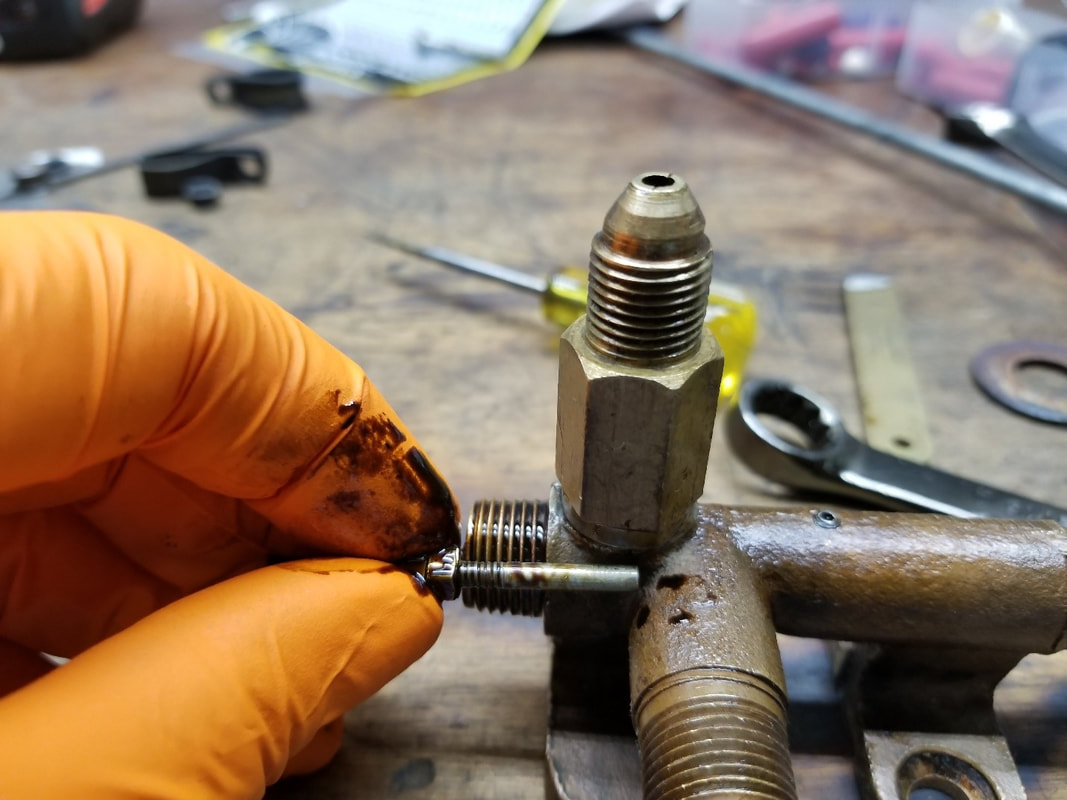 The shortest the secondary piston and metering rod can be is to a point where it gets right past the opening. This will also provide the most oil to the cylinder. 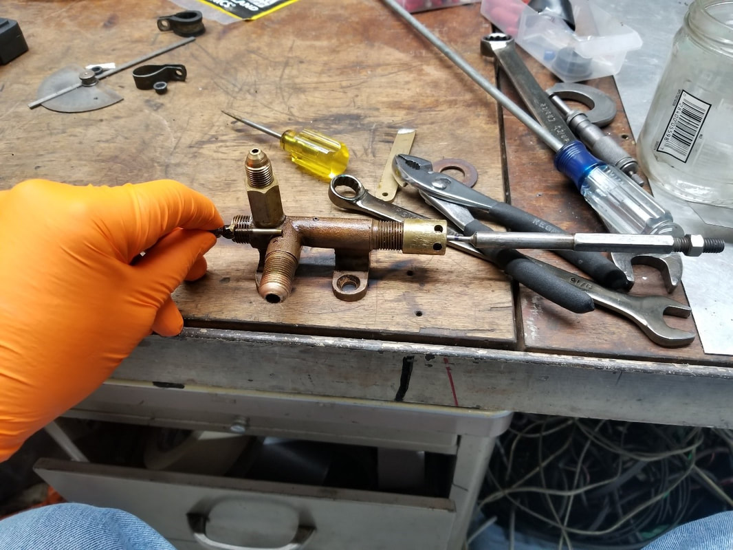 The absolute longest would be a point where it almost reaches the intake port. Very little oil will be pumped with this setting. 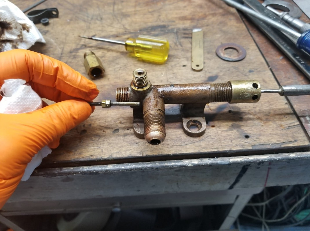 The rod is adjusted by moving the nuts in or out and then tightening them against each other. 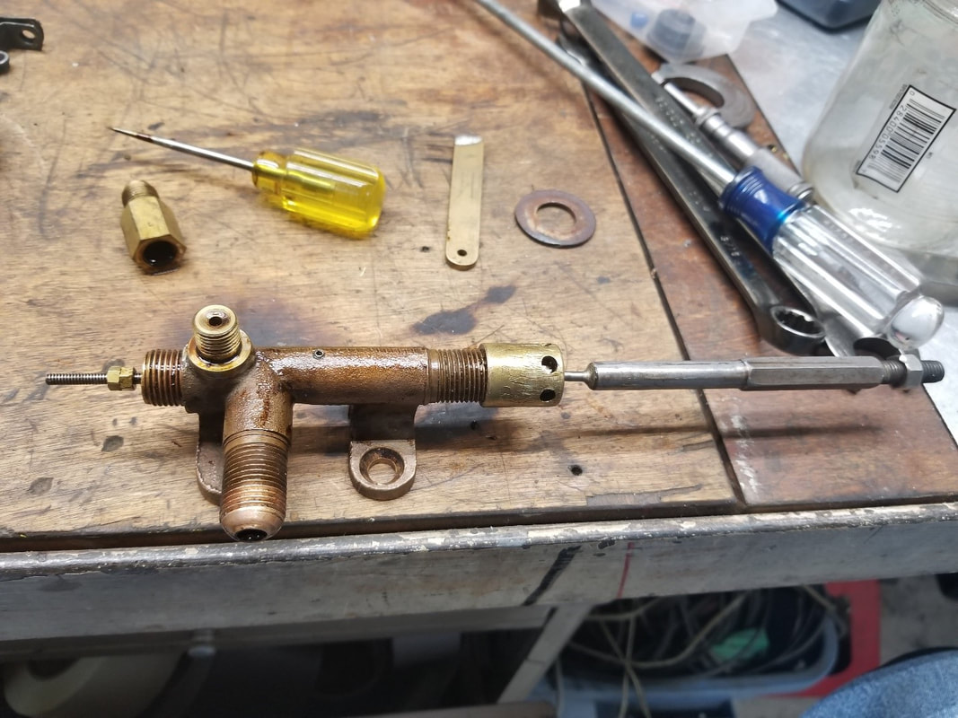 To set the limit of the primary piston, place the metering rod towards the end of the hole, push in the primary piston until the two meet and mark the spot with a marker. 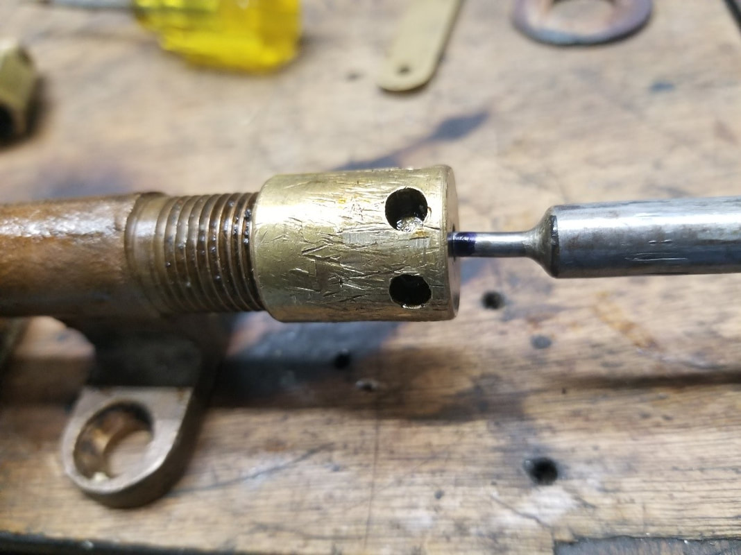 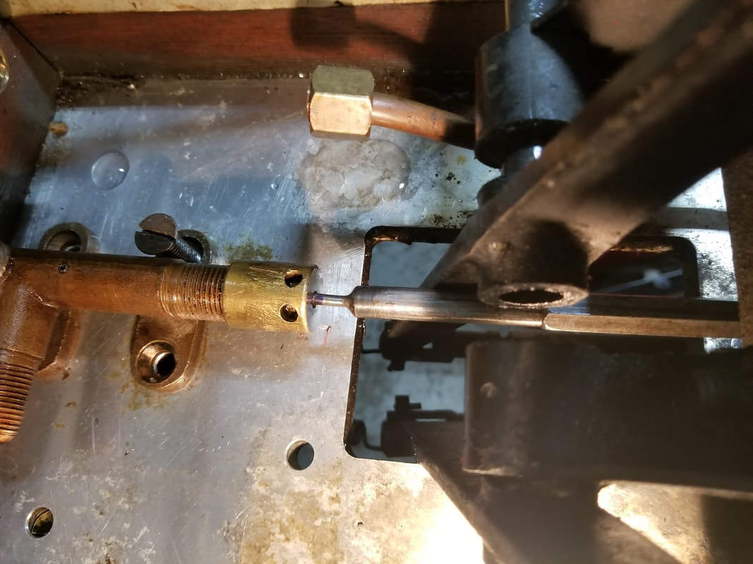 Once back in the car, screw the piston into the mount until the most forward motion reaches the mark. Brass Cleaning As There is a lot of Brass/ Copper on this car, polishing it will take a fair bit of time. Polishing very tarnished Brass/Copper is best done with a soft cloth polishing machine and red rouge for a rough clean. White rouge on a finishing cloth seems to leave a build-up and the finish does not improve. The likeliness for a Polishing machines to grab and throw parts to the ground at great velocity is directly proportional to their fragility and replacement cost. Polish The best way I have found to clean by hand is through the Wizards product line. A buddy introduced me to Wizards Metal Polish, which is an impregnated piece of cotton. It worked well but not nearly as well as when I added Wizards Metal Renew to it. Other products tried were : Mothers Billet Cleaner (Good) Brasso (Poor) Most products sold at flea markets and products like Oxy-clean have found their way into the trash bin. Saving the shine As of 2019, I have not found a suitable product that works. I stayed with Wizards Metal sealant as it came in a package with the other Wizards Products. It seems to help a little. Eastwood has a product in a spray can that almost looks like a clear coat. Neither really kept the Brass from turning yellow and the Eastwood product required the buffing wheel to remove it. Paint By the end of 2018 the paint started coming off sections of the car in sheets. On other parts like the hood and the front, there was a lot of burn damage. For a short time, I considered stripping the car down completely and have it repainted professionally, but veered away from that as the vehicle is getting a lot of use and the time it would take to do so would probably turn into a full restoration: as well as the slim chance of a fine pint job remaining that way for any length of time lead me to search for an alternative Gloss paint that would be durable. I eventually settled on Sherwin Williams Industrial Enamel. My Neighbour Arthur helped with prep and paint of the large flat section, as I did not want brush marks. The hood is a combination of prep styles as well as some brushing and some spraying. The paint on the side was in very poor shape, and was not sticking to the wood at all. The passenger side seemed to be less affected by it. Early attempts included trials with and without primer as well as brushing VS spraying. Arthur was of great help here. Eventually, we settled on a sand-able primer and spraying the enamel after making sure the primer was smooth. The gloss is not nearly what I would expect from automotive paint but I will try wet sanding it next winter. It takes a long time to dry. The dark blue stripe with the 1/8" light blue stripe within was achieved by putting a 1/8" piece of masking tape and paint the dark blue over it. I found that this paint came out very well if the masking tape was removed immediately after painting, as it allowed the paint to flow. Multiple coats of enamel tend to cause it to crinkle, probably since it takes so long for this paint to dry. Resources Steam Oil: Siphon-a-min 1000 Brennan oil 970-247-3054 Machining of complex parts: Rempco 231-775-0108 Boiler repair: Don Bourdon (802) 457-3787 Tank Sealer: CHEMSEAL B2 TANK SEALANT CS3204 Brass: Wizards 3004.2982 11011 Metal Polish. Wizards Metal Renew_Silver Polish, Aluminum Car Care, Motorcycle Copper Cleaner. Wizards 11021 Power Seal Metal Sealant. 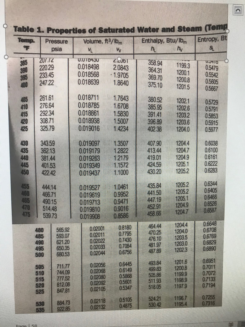 Fuel Filters I installed 2 fuel filters/water separators in 2017 after noticing how much filth got into the system. I feel the pumps, Fuel automatic, Check valve and steam automatic will be well served with clean fuel. In addition to that, the 55gallon drum holding the Jet-A seemed to not get rid of water after rain, so I had some worries there. Parker industries introduced the RACOR SNAPP 2 micron water diesel fuel separator. It is a one piece unit of which the insert is easily replaced. Water settles in a transparent bowl and is easily drained. The valve is the main shutoff at the fuel tank. Fuel was unable to pass through anymore. For the Hexane system, I installed a RACOR 110A 10 micron fuel filter. It can be pressurized and it was plumbed in with copper tubing. It should perform to 35 psi 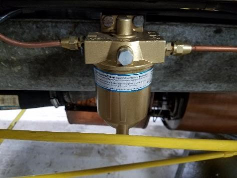 Update 8-17: the main fuel system has performed extremely well. For some reason, I have been draining a lot of water from the main fuel system and the filter will likely need replaced already. I don’t think it was as crucial for the pilot fuel JRG means it originally came from Goulds. When assembling the bottom part, the system will bottom out when about three threads are showing. The assembly will be less than half a turn past where it needs to be. There is not a lot off travel and there is a lot of tension on the spring 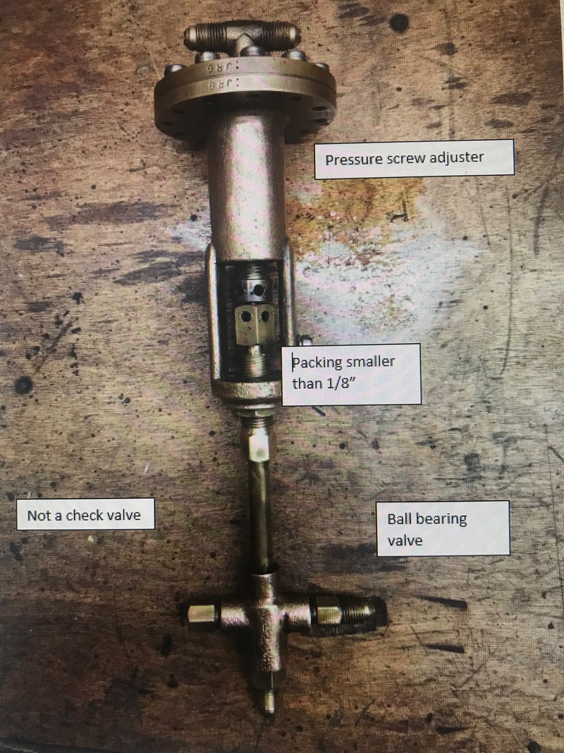 Exhaust System.. The initial system had big gaps from where the engine pushed it out before the engine steam intake was shortened. Welded the system closed to where the steam discharge pipe came in. I’m puzzled with the pipe. It is simply soldered together and seems to hold fine Tailpipe. I had soldered the tailpipe in the past/ it did not hold so I ended up welding it (TIG with High Silicon Brass rod from mcmaster) Pilot Light. Bottom unit was a Propane setup. I converted it back to Hexane. Pilot body by Don Bourdon 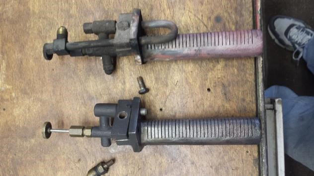 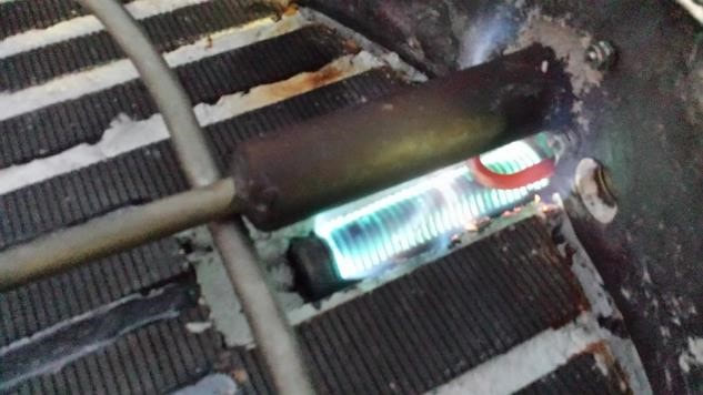 Built a new needle from 1/8 steel rod using lathe grinder. Threaded it to standard #6 and threaded the casting accordingly. It needs to stick out past the seat as it guides gasses into the casting. It is easily bent on removal 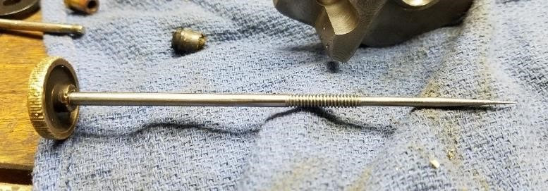 Sight glass (Gauge glass). An extremely useful study source is the klinger product catalogue at http://www.klinger.kfc.at/index.php/en/component/jdownloads/send/3-product-catalogues/19-product-catalogue-gauge-glasses The unit on the steamer is as size 1B reflex gauge and can be found at mc master at https://www.mcmaster.com/#gauge-glass/=1cljafz The following came from Pat Ferrell in Washington state after a facebook inquiry: I do use the McMaster reflex gauge gaskets, as they are a good value and they fit well. I use an antisieze on my gauge's bolt threads and I torque them starting from the center bolts like torquing a car's head gasket. Tighten a little at a time. I torque them when the gauge is cold, and then I re-torque them after the gauge has been fired and has cooled down again. I re-torque them every spring as an annual service. How many pounds? I torque them firmly, as I don't use a torque wrench, I don't want to guess the torque. In the 33 years of steaming, I have never had the quality of a reflex gauge glass degrade from use. Through the years I have lost about 3 gauge glass gaskets while on the road. I always carry spares with me. 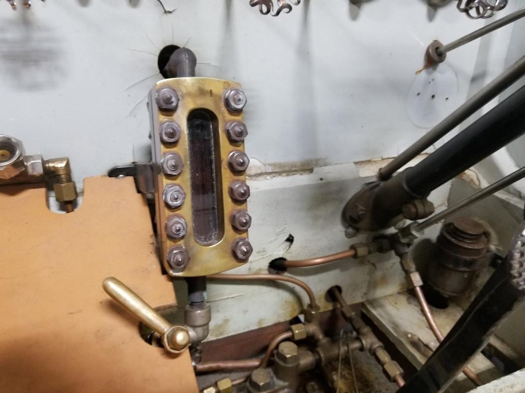 Burner (Baker Style. Made by Blazik) Remove and install: the burner will not come out with the car at its normal level. Lift the body and install two pieces of 2x4 to keep it up. A long enough piece of plywood held up in two spots will help finesse the thing out of the car but is indispensable to tweak it back in Disconnect the steering bar to give more room 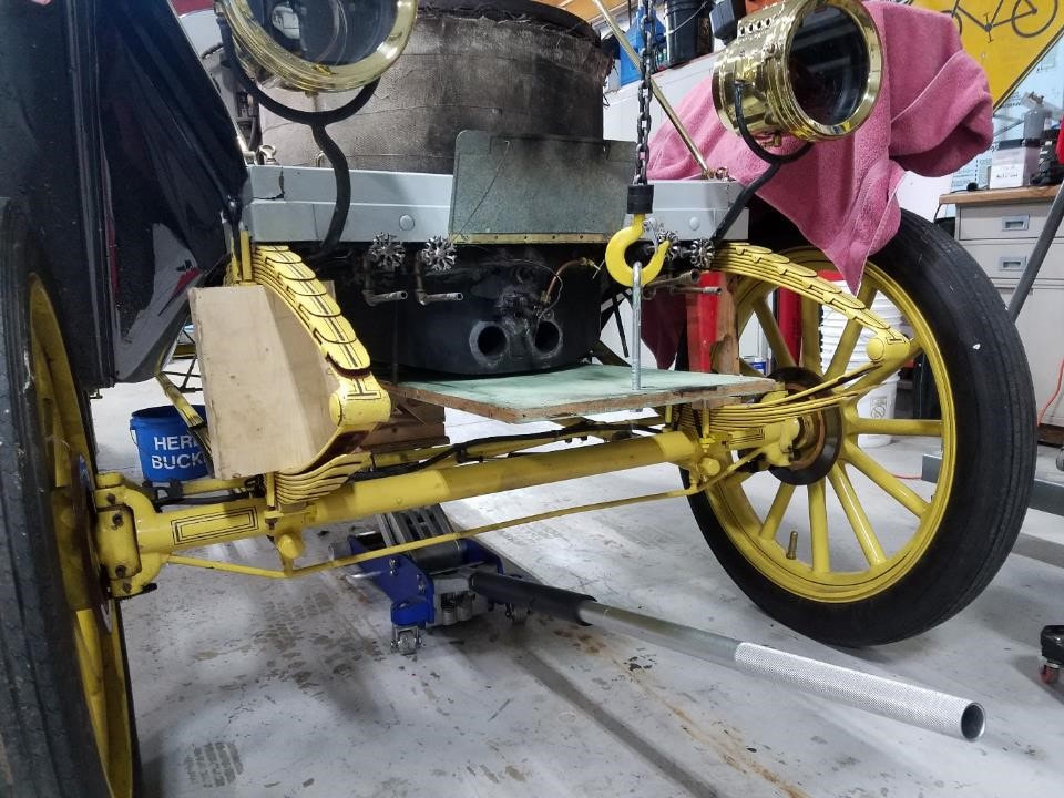 Burner make-up. The burner sits in an insulated pan. The easiest way to take the burner assembly out of the pan and put it back in is by doing it upside down. The gas diffuser is simple but the pipes are above the pan. If the pilot goes out and raw kerosene is blown in, there is no way for it to leave other than by burning it off. I used muffler repair dope to seal the halves together and furnace cement to seal up everything else Use masking tape to cover the slits and protect them from cement. Use insulation between pilot and burner “Imperial hi-temp stove and furnace cement, Grey” seems easy to work with Everything is screwed together with #10 button heads 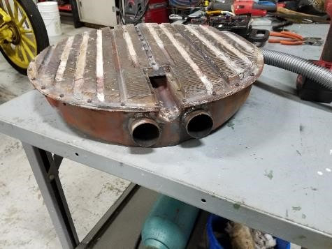 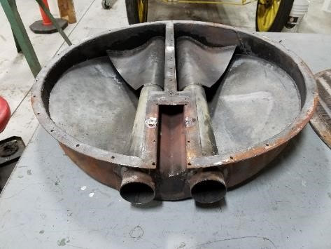 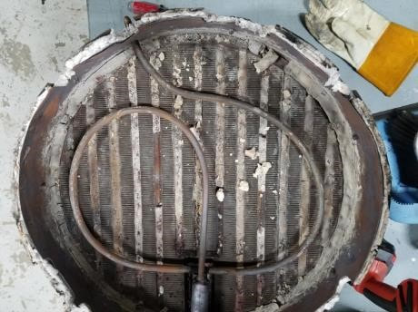 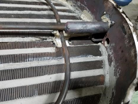 Hubcap. lost a hubcap in Iowa, decided to make a new one from ultra machinable brass from mc master 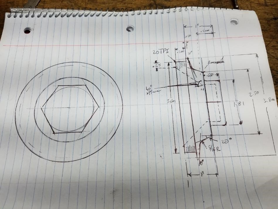 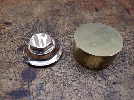 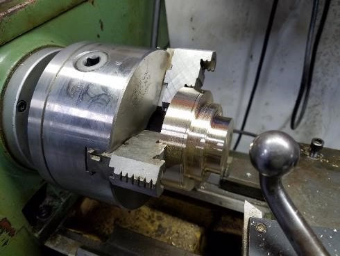 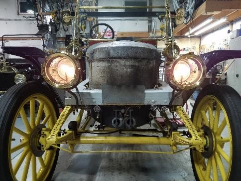  Brakes (Front). Front brakes are Tokico A1 2-pod systems. They were used on a number of Kawasaki and suzuki 500 models in the 90’s. Seals are skf 22441 (3.25”X2.25”) 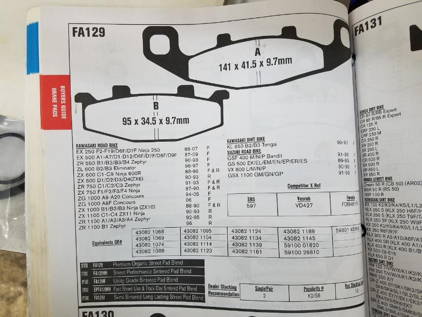 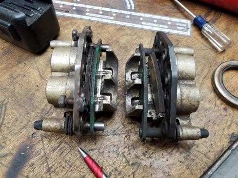 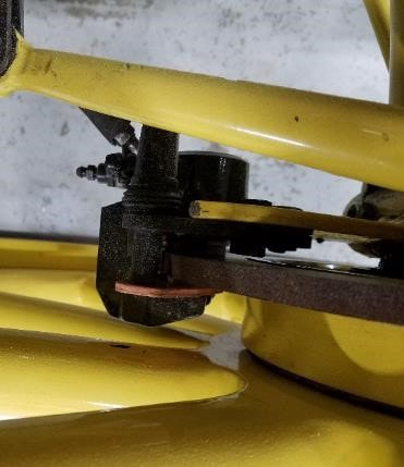 Brakes (rear). The outside brake is for parking and emergencies. As you pull the handle, it will get tighter and you may have to stop completely before it releases. The wheel can be removed with everything in place but you will need a wheel puller. Adjustment is done through the large yellow screw in the back (Pic Below) and the adjustment barrel is standard tread so to tighten, you have to push the ears up on the driver-side and down on the passenger side. A grease seal was installed in 2018 to try and keep oil off the Brake shoes 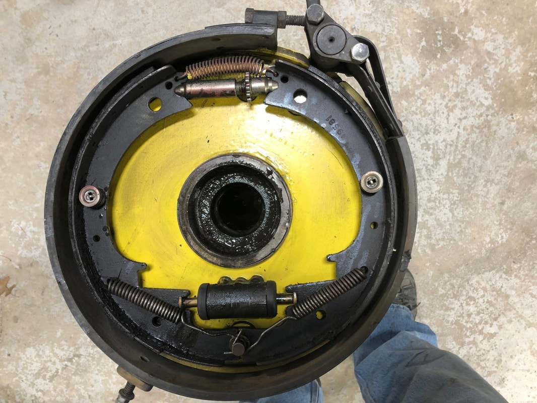  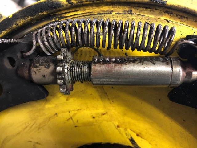 Tires. Contrary to what I thought, Tire and Tube repair on this car is not likely something that can easily be done on the side of the road 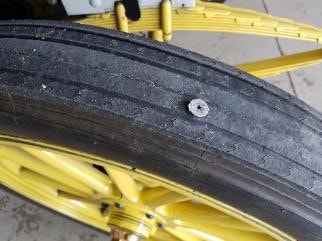 In August 2017, I ran over a screw with the front wheel. It was on the last day of the Vermont tour and the tire did not go flat until the next morning. After eighteen years of use, the tire had very little tread left so it was time for replacement anyway. Once Home, I removed the tire but was unable to get the new one on. The design calls for the inside part of the tire to be seated on the edge of the rim before the valve can go in. there is very little clearance between the tire and the three-piece rim so putting the tire on at an angle, allowing the tube stem to go in, is out. Eventually, Dave Vaughn put the tire back on the rim but in the process, ripped the new innertube. Also, between Dave and especially myself manhandling the tire and the rim, we did a lot of damage to the paint on the wheel. As the inner- tube needed to come out again, it was a good opportunity to rethink tire management basics Tire size: 36X4 Pressure: 60PSI min Vendor: Universal Tire Wheel: all with steel three-piece Rim Tire replacement consists of some major steps
Tire removal I have found it easier to keep the wheel on the car for this Remove the valve stem Mount the clamps on the tire and push the outside of the tire in enough to allow the outer rim to come off.  Remove the set screw on the rim lever and loosen the nut As gently as possible, remove the outer rim. If the tires have been on the car for a long time, “gently” will include a prybar and the rim will get distorted If the tire has been on the car a long time and has dried out, it may be possible to evenly slide it of the rim. If that is the case, push the valve into the rim before removing the tire. Next, see if you can move the tire off by hand. Even when using the clamps, try to remove them every so often and use your hands. This is an extremely tedious process that will see no more that around 1/16” progress per revolution. place your clamps to push the tire off the rim and start pushing the tire off the rim   The rim is a Three-piece design. Loosening the little screw and tilting the lever outwards allows the rim to come off… in theory. In the model R, the wheels had not been touched since the car was built and the rim was rusted stuck in the groove. It took a substantial amount of effort to get it out and the rim elongated  After cleaning the outer rim and the channel in the main rim, I marked bent-up areas and built a jig for the press to help get it back in shape. It takes only small amounts of travel to get the rim to bend and requires frequent fitting . I ended up drilling and tapping two holes in the rim (10-24 hardened bolts) (5/32 drill and 10-24 tap) and connecting two L-brackets and subsequently pulling the parts together with a ¼ threaded rod (Use a thick nut) after liberally coating the groove with never-seize 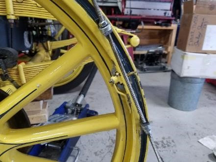 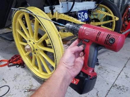 Mounting the tire. DO NOT INSERT THE INNER TUBE Slide the tire over the rim as far as possible. Use the tire-me-bob and a mallet to pound the inside on the rim past the first lip. You can then put the outer tire on and pound the entire blessed thing in. use the clamps to help. Progress will be tedious and, unfortunately, you will chip paint Continue until the tire covers the valve hole 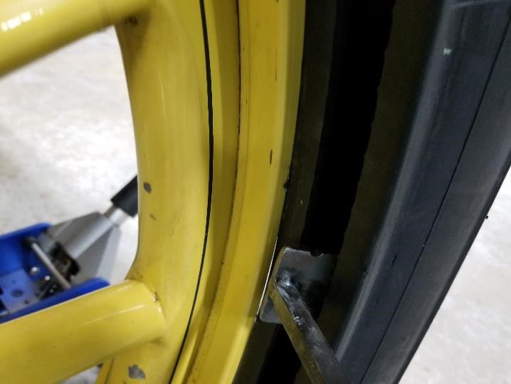 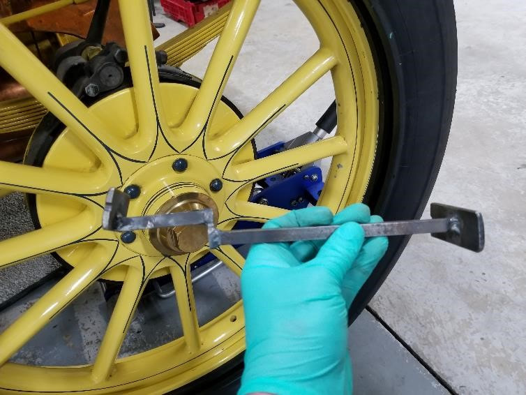  At this point, install the rim. You can leave the pulling mechanism on it. Inflate the tire with a rubber-tipped air chuck until it seats on the interior part of the rim. As the outer rim is lubed well, you may be able to work it out with a large screwdriver, pushing the tire in enough in the process without distorting the rim Put reverse rolled duct tape in the groove where the rim fits through so that no air can escape Blow up the tire with the airchuck until the outside tire pops off Place the inner tube as outlined in the next section Inner tube replacement. Remove rim as described earlier. DO NOT REMOVE THE ENTIRE TIRE if you can avoid to do so Clean, reshape and refit the outer rim If you’re only replacing the inner tube or if the tire is stuck, take the valve from the tube and use an air gun to blow up the inner tube and allow it to push the outside of the tire off the rim. Even if the inner tube has a very large hole in it, this will work   Place the 1 1/4” dowels between the rim and the tire. Push out the valve stem. It is a rubber stem and is a press-fit. Remove the inner-tube, working around the dowels. If you are only replacing the inner tube, don’t remove the rest of the tire Use baby powder Once the tube is in place, again inflate it to allow the tire to fit back over the outer rim, then pop it over the inner lip with screw-able wood vises as shown. Use of a hammer and dowel will help getting the area in between the wood vises to comply. There is extremely little wiggle room once the tire is on. Push the tire in far enough in so the outer rim will go back on. Replace the outer rim and gently blow the inner-tube to set the tire on the rim. Replace the valve and blow the tube to at least 60PSI Keep a little air in the tube while pounding the tire back on the rim to avoid getting it pinched between the tire and the rim Roof. After return from Maine in 2017, we noticed the front bow had snapped in two. On inspection, the wood appeared to be quite brittle but I felt a suitable repair repair would be to drill a ½” hole in both ends and insert a ½” tube into the holes, putting it together that way. It should be structurally sound and undetectable as it’s covered up well  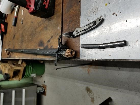 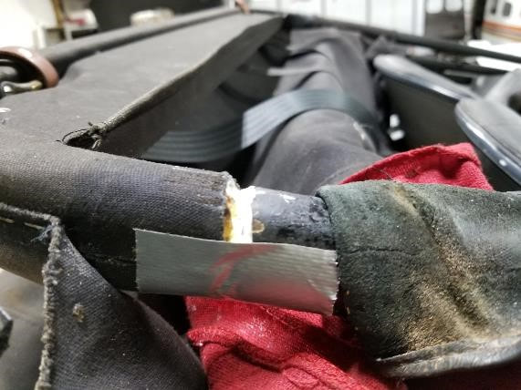 Engine removal 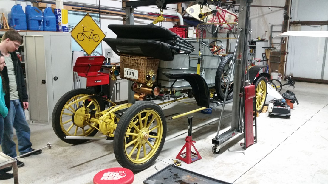 The easiest way to remove the engine is to do so with the rear axles attached. Remove the drip valve from the engine, screw in a ½” npt pipe around 6” long. the one in the box has a solid insert for added strength. It will support the engine on a floor jack Place the lifting strap under the body but on top of the exhaust pipe. Connect to the hoists and remove all slack I took the springs off with the axles this time as they had sagged and needed removed. If this is needed again, I would likely leave them on the car Remove brake lines, pump rod, exhaust and the steam line at the coupler Remove pitch pole nuts. They are mounted on a threaded rod and one of them did not go back on well Place the rolling floor jack under the pipe you threaded in and keep the handle under the differential lift until a slack is removed Unbolt engine from front strap and pull strap of the engine Lift the body until there is a gap between the spring and the axle and roll out the entire assembly Reinstall Reassembly is easier if you put the wheels on lock jacks to help manipulate the assembly 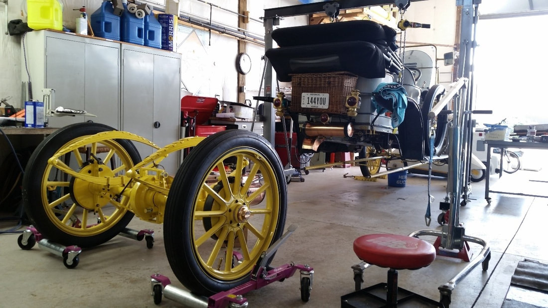 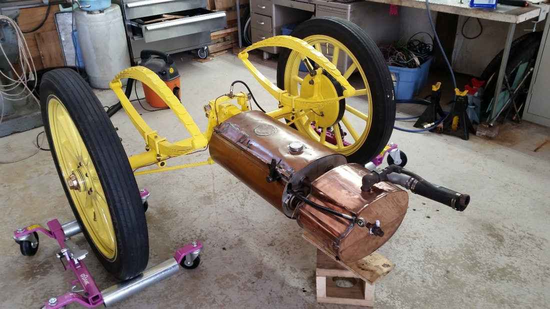 - Maintenance log. This is the maintenance log I have kept since I acquired the car. 2013. We bought the vehicle from Phil Lewis in August 2013. This was my first exposure to steam and most of the year was spent just on learning. Met Robert Wilhelm, Mr Marshall and his steam museum in Maryland and towards the end of the year, while in Maine, I met the Stanley Steam team at the Museum there. I did not steam the car up for the first time until the end of the year. Installed replacement Burner Phil had acquired through Allen Blazik. Mapped plumbing. Converted Propane pilot back to hexane. Tried to fix leaky valves. 2014. 2014 was generally spent learning how to fix valves and pumps. I experimented alot with different packing material. Replaced packing in water pumps. Replaced Packing in fuel pumps. General cleaning and polishing. Many local rides. 2015. Machined water pumps for balls to run at 1/32” clearance. Replaced with Delrin Balls (7/16”). Replaced Packing again. Disassembled Oil system, cleaned and fixed oil tank where a screw was put through it, disassembled oil pump and reassembled to different specs. Disassembled oil pump again due to intermittent lack of pumping oil. Removed a check-ball that did not show on the drawings, it did not fit and was probably added in error. As the result of an oil leak, found damaged gears in the differential spider. The drive train completely removed and disassembled. Broken parts sent off to Gilbert Hall at Rempco in Cadillac. Rear suspension sent to Detroit Spring to fix sagging. Finished the Canadagua Tour this year, which was our first Steamcar tour with no real issues. 2016. Repaired plugged fuel line. Reassembled engine with some newly built bearings (Rempco). Reused valves and repacked guides. Reassembled rear end, refitted axles and clearances in repaired housing (Jim Wright) and powder coated parts (Creative Powder-coating). Repaired water tank. Had multiple issues during Maine tour. Pilot kept going out. Squeaking in the pumps and fuel delivery failure eventually forced us to trailer it back on the very last day. Replaced pilot casting with new one from Bourdon and built a new needle from 1/8 steel rod using lathe grinder. Threaded it to standard #6 and threaded the casting accordingly. Main fuel valve at the tank was completely plugged up. Much squeaking in the pump assembly resulted in repacking with more high pressure packing from Mc-master. Iowa Tour brought more issues with pilot and leaking main throttle. We finished the tour with poor fuel delivery issues (plugged valve). -Participated in two tours: Kingfield Maine put on by the Stanley Museum and Prairie du Chien in Iowa. Neither were free of problems but the car performed well 2017. Removed burner, disassembled burner. Cleaned and reassembled with new bolts and nuts. Disassembled the main fuel vaporizer completely and flushed the system. Replaced into the burner assembly with hardened bolts. Removed and disassembled throttle. Straightened shaft, machined cone, reassembled and tested. Seated with minimal leakage. Shaft moved freely after repair. Replaced the assembly from the boiler to the throttle with a single medium thickness black pipe, connected with a Swagelok part number SS-8-RSE-6 elbow. Got ¼ pipe and elbows as well as “Key Graphite Paste” from Mc-Master to start sealing piping. Extended the whistle valve and redid that assembly. Re-seated both valves for the sight glass and re-seated the blowdown valve into the exhaust The smoke hood had started to crack at a point where it did not match the boiler hold-down bar. The bar was re-positioned and the top TIG welded. Removed the fuel automatic and disassembled the bottom part. Repacked shaft and reassembled. The entire assembly was filled with water and tested to 750 PSI. Steam automatic restricts at 550 psi and closes completely at 600. Checked for leaks. Because of ongoing poor performance on the water pumps, I decided to replace the packing in the water pumps with #247 John crane packing from vintage steam products. The check valve cap broke and I remade one. Took apart fuel automatic. Remade nylon valve. Fished extra bearing from pipe that had occluded the system. Re-seated check valve and cleaned the system out. Reassembled and set for 130 psi. Don Bourdon is building a new boiler. Picked up 8-17 and put in storage. Removed old electric box for propane equipment. Ran electrical wire for brake lights to wicker basket. Replaced brake lights with LEDs. Installed water separator for both main and pilot systems. Plumbed acetylene tubing to the lights from the running board and hooked them up. Made a new hub cap. Exhaust leaks. Sealed up leaks in the exhaust system. Welded the front part and screwed the rear end together to get rid of all the gaps. Rebuilt the tailpipe by welding it rather than soldering it. Rebuilt the front brakes (Well, Mike from Kennedy’s did as he found the parts) turned the rotors down .020 which made the units fit better. Repacked the front wheels and replaced the seals. Removed water tank and had it fixed by Thomas radiator. It was still leaking a tiny bit after last year’s repair. Replaced some of the covering on the smoke hood. Late 2017: Replaced front tire right side (left from front). Made bigger bolt hole and tighter treads in front right kingpin (left seen from front). Put in 5/16 soft bolt, kept upper hardened bolt in place. -Participated in Vermont tour with no issues other than running over a screw on the last mile of the last day, causing a flat tire. 2018. Replaced rear tires, a job I hope never to have to do again. Fixed front roof bow which had somehow broken. Removed water reservoir as it was leaking again and brought it to Thomas Radiator to see if they could fix it. Fuel starvation again due to main fuel valve plugged up. Cleaned and reinstalled. Replaced water separator as it had gotten so dirty you could no longer see the bowl. Tightened all bolts holding pump housing to the car. Repacked water-pumps again and found pump-shafts to be concave, likely leading to premature failure. REMPCO machined new ones from hardened material. They need oiled after each use to keep from rusting - Participated in Pennsylvania tour, hosted by the Auburn Heights and Mr Marshal as well as the Washington, Missouri tour put on by Dick Friedeman and Joe Graziano. Both were trouble-free. 2019. The Water reservoir started leaking again. Top and one of the sides was removed. Copper was thoroughly cleaned, and bottom was welded back together with poor results. The rest was soldered back together, and aircraft tank sealer was used to waterproof the seams the top was then soldered on again The steam siphon system was repaired as described extensively in that section. Rear axle shafts were re-machined to allow more wheel clearance. Oil seal system fabricated on the outer axles to keep oil out of the brakes as described in that section. Steam box cover replaced with new one from Hokes. Driver side rear perch pole nut repaired. A lot of the worst paint damage was taken down to the wood, re primed and repainted with Sherman-Williams industrial enamel. The flat section on the driver side was painted with an airless system. The throttle was removed and rebuilt by Gil at Rempco in Cadillac. The smoke hood was remounted and the holes were refilled with refractory cement. The kingpin in the Passenger front wheel was tapped and fitted with a hardened bolt, similar to the driver side. The wedge in the lower part remained. The Fuel filter was replaced. Replaced the hinges on the windshield with reproduction Brass-era model-T hinges. Fabricated a new end to the siphon hose out of brass and copper parts. Eric sewed a patch on the driver side shroud as the material had worn through and the rod started coming out. Learned to pinstripe and did quite a bit of that. Repair Guide. Water pump check valve bolt. Check ball clearance 1/32”. Adjust by machining excess off lip. Raw material: 3/4 “hex rod from McMaster. 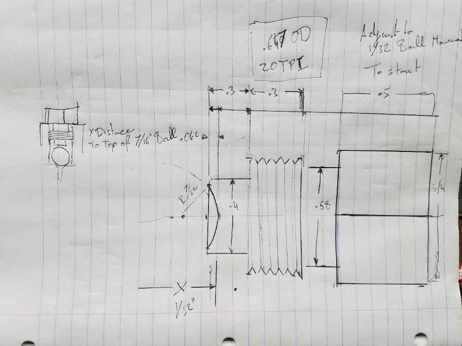 The tank is made from copper sheeting soldered together into a shape that fits under the seat. The seat top is removed with wood screws under the base. The water return line has to be removed in pieces and requires some creativity as shown below. The siphon hose and the water feed also have to be removed before the reservoir can be removed 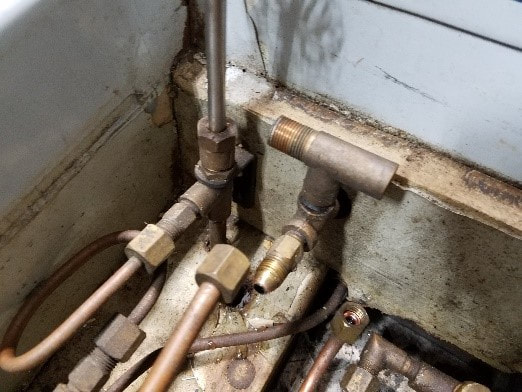 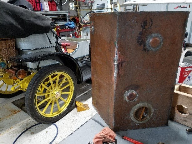 The water tank has been seeping since I've had the car but it had gotten worse in 2017. I had tried to fix it at that time but it leaked again in 2018. I removed it again and Thomas radiator went at it, but by the fall it was leaking again. I removed the worst side, cleaned it and attempted to weld the bottom with extremely poor results. I ended up soldering the thing back together and sealing the seams with "CHEMSEAL B2 TANK SEALANT CS3204", which is extensively used in aircraft pressurized cabins and fuel cells. Instructions for use: https://www.youtube.com/watch?v=bbNqw_qqCPI The top edges were cleaned and the top soldered back on. Function of holes and tubes in the tank clockwise starting with the small hole towards the top center: sight glass. steam powered siphon, overflow, main water feed.  A simple device, just make sure the ball bearing does not fall into the body and plug the passage. I was surprised with how much dirt got into it, likely leading to its extremely poor performance. 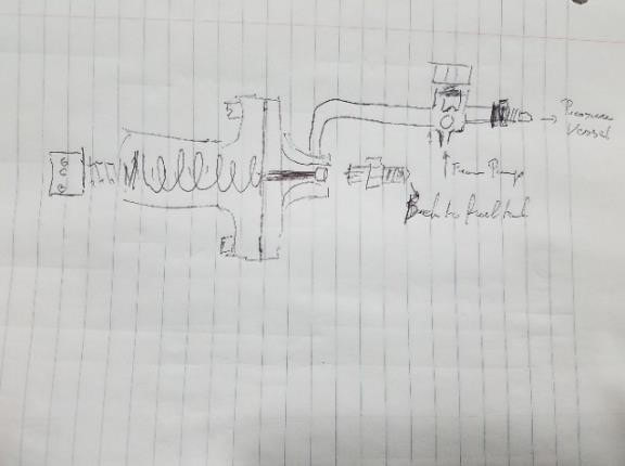 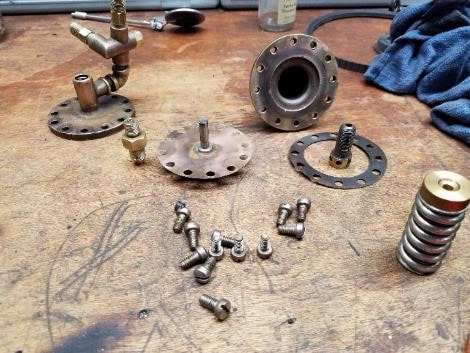 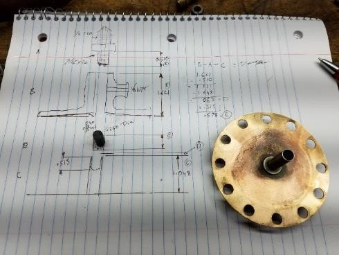 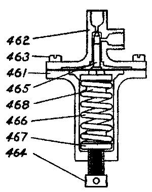 The black plastic part is MDS infused nylon, turned to fit snugly in the hole. The diaphragm should seat flush on its base and the nylon valve should just touch the seat. Important: the one-way valve bearing ahead of the assembly will easily travel down the pipe and block the entry to the assembly. If the ball shows up missing during reassembly, that’s likely what happened. Pressure setting is extremely simple. Pump the handle. If you reach past 140 psi with a steady stroke, loosen the spring tensioner. If it does not build up enough, tighten it. The throttle works pretty ingeniously. Steel shaft, steel barrel and brass seat held on through a press fit with tiny roll pins. Has to be removed for disassembly and hole has to be realigned with exit hole for it to work. 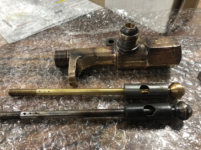 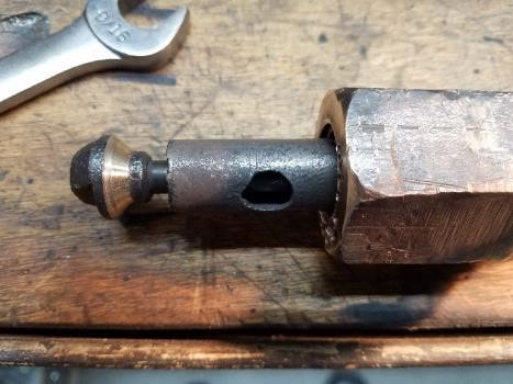 The 2019 rebuilt throttle with the original slide. The slide was also made a little shorter and the steam feed pipe a little longer to allow for better clearance. The three divots have to line up with the out port. 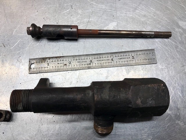 |
Archives
December 2022
Categories
All
|
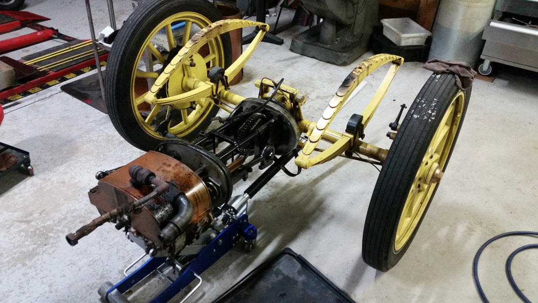
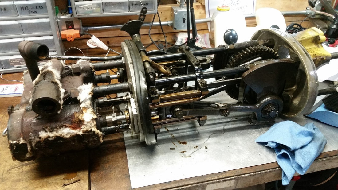
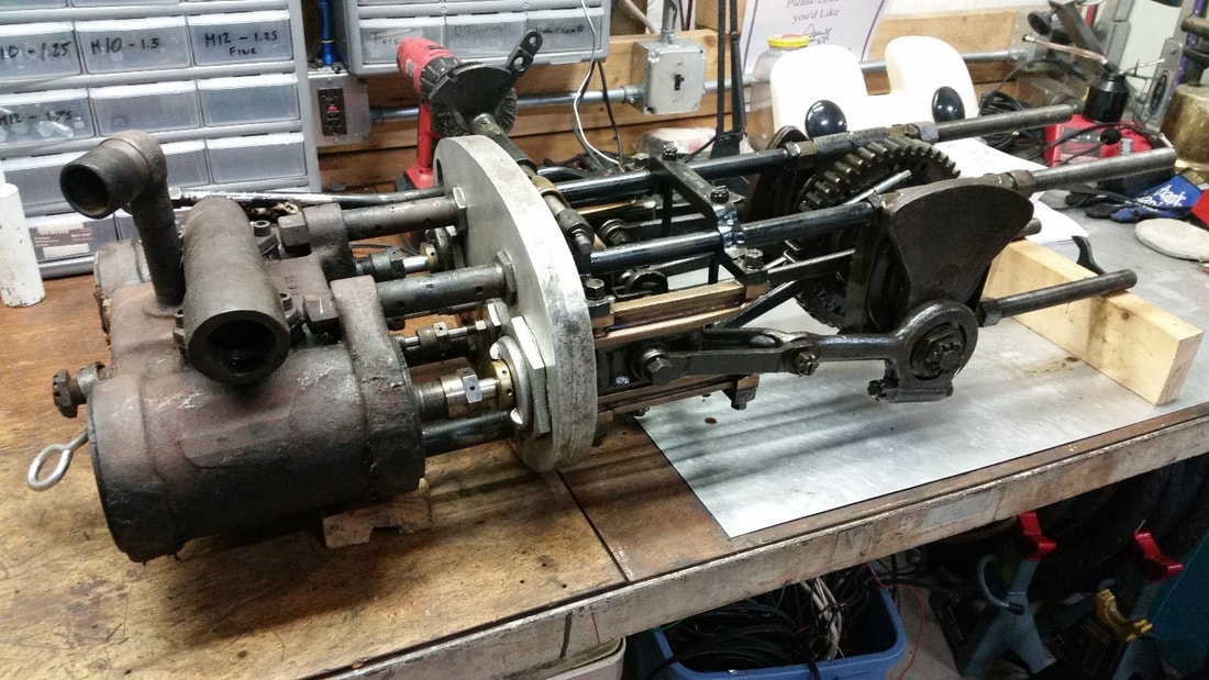
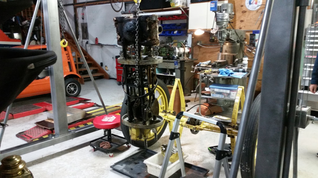
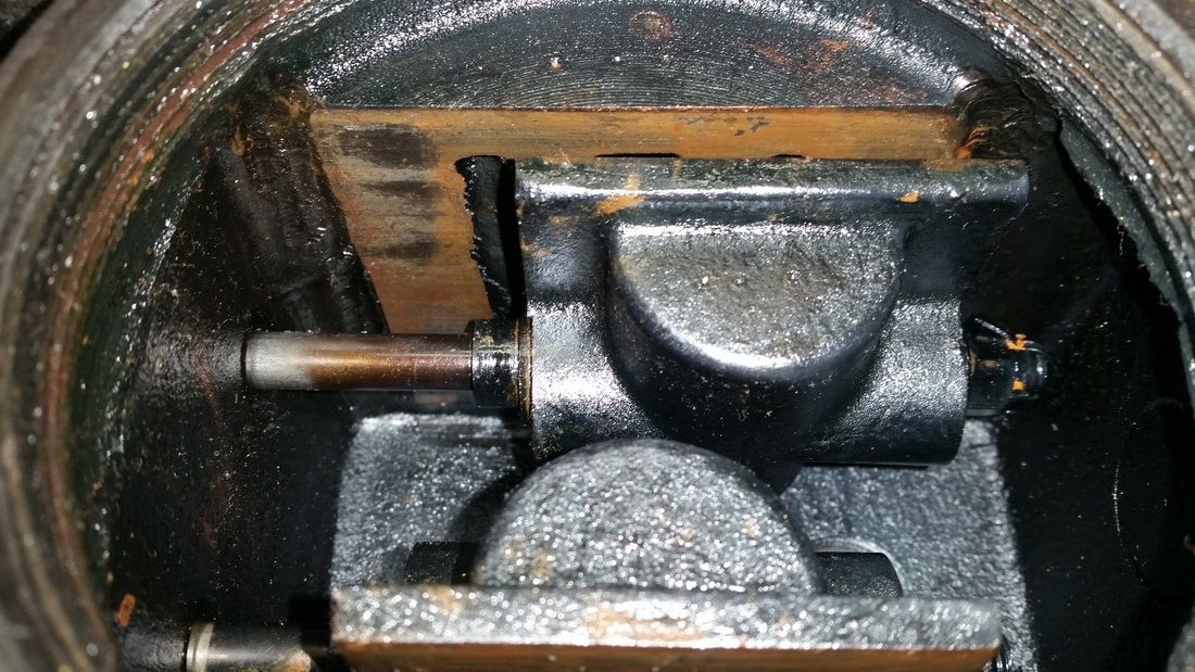
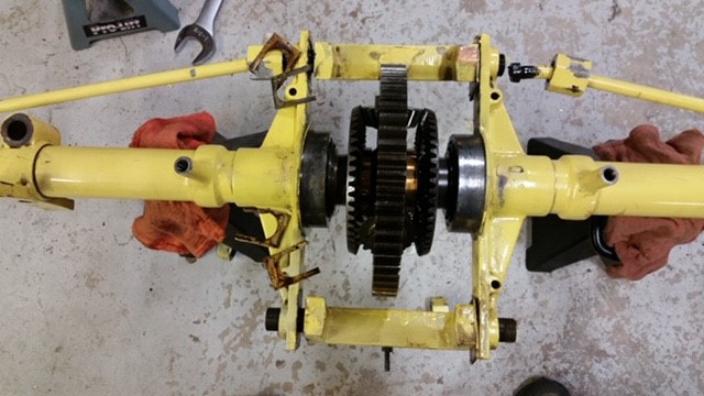
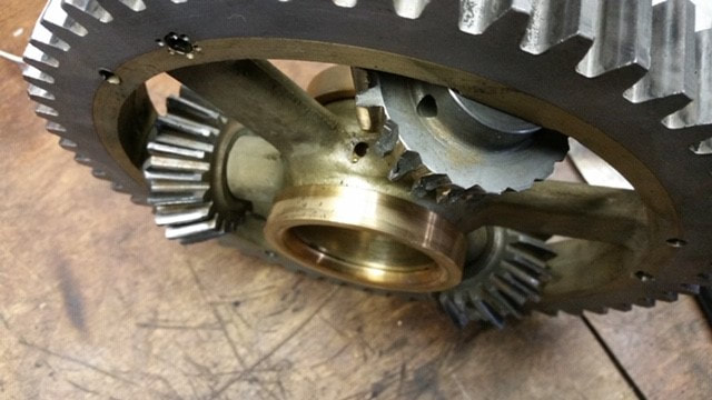
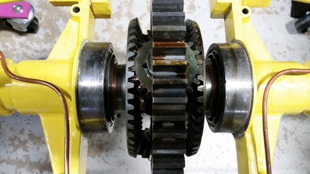
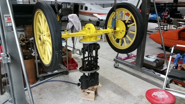


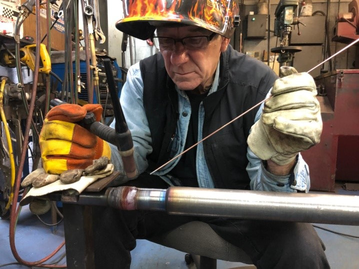
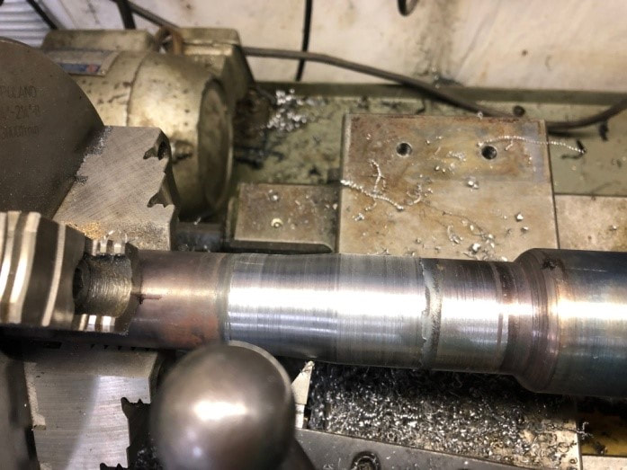
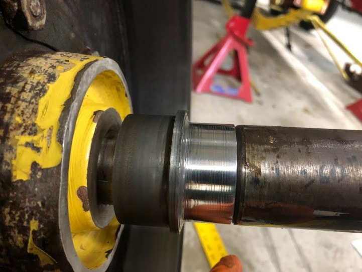
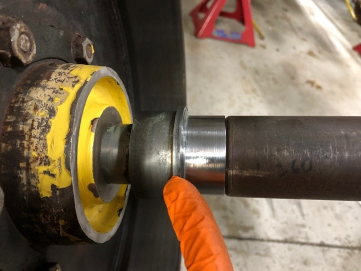


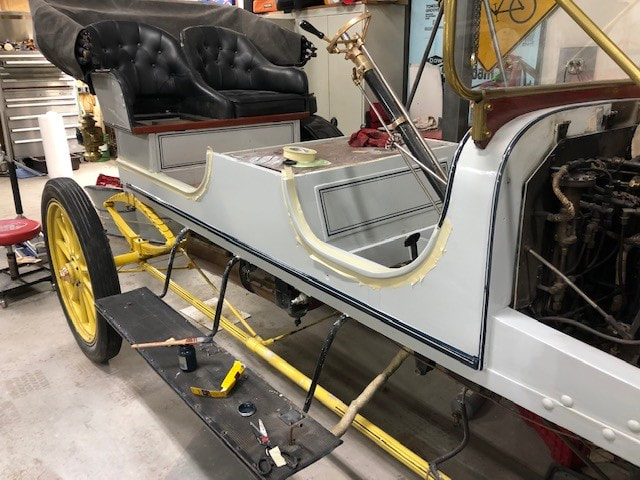
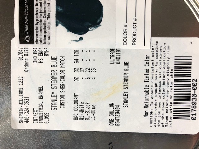
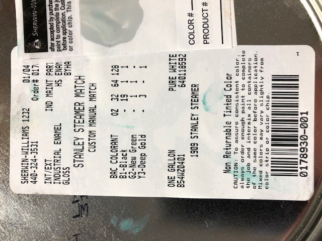
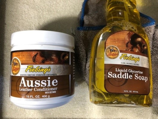
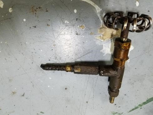
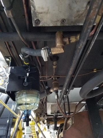
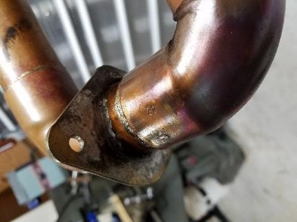
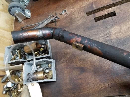
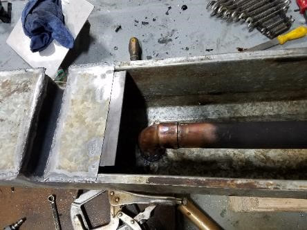
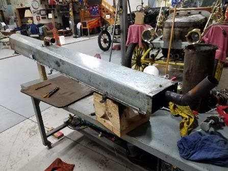
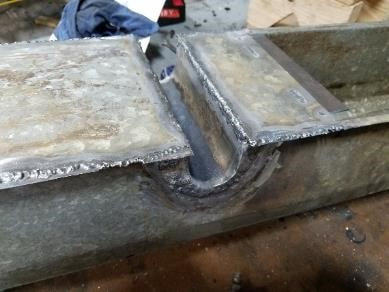

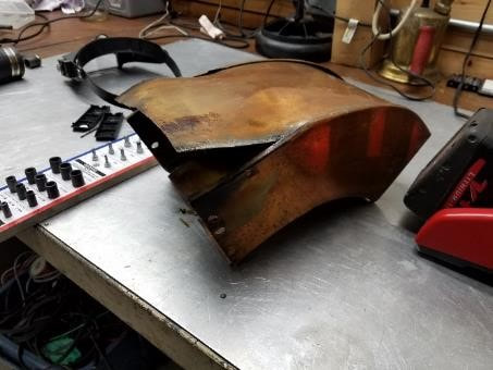
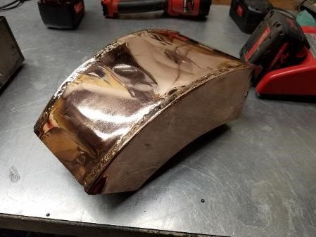

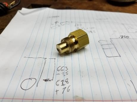
 RSS Feed