|
Steam Car Network
|
|
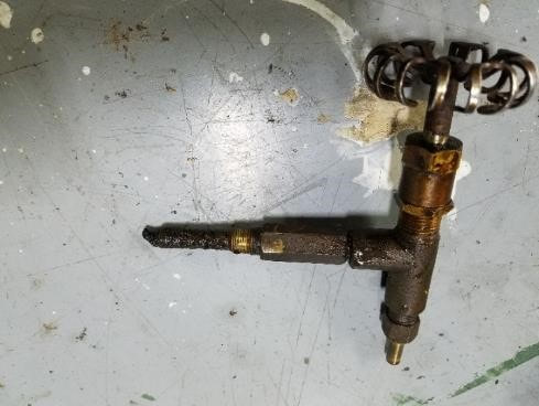
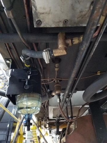
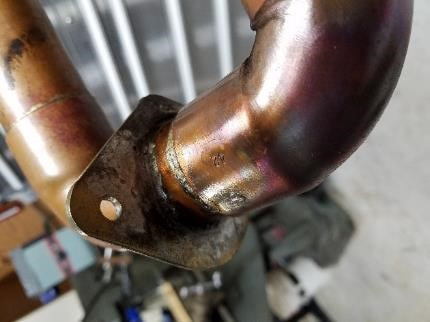
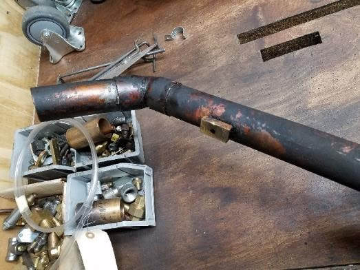
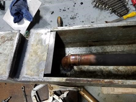
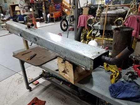
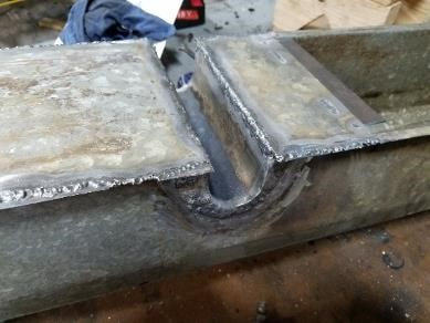
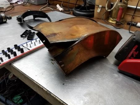
Fuel Filters I installed 2 fuel filters/water separators in 2017 after noticing how much filth got into the system. I feel the pumps, Fuel automatic, Check valve and steam automatic will be well served with clean fuel. In addition to that, the 55gallon drum holding the Jet-A seemed to not get rid of water after rain, so I had some worries there. Parker industries introduced the RACOR SNAPP 2 micron water diesel fuel separator. It is a one piece unit of which the insert is easily replaced. Water settles in a transparent bowl and is easily drained. The valve is the main shutoff at the fuel tank. Fuel was unable to pass through anymore. For the Hexane system, I installed a RACOR 110A 10 micron fuel filter. It can be pressurized and it was plumbed in with copper tubing. It should perform to 35 psi 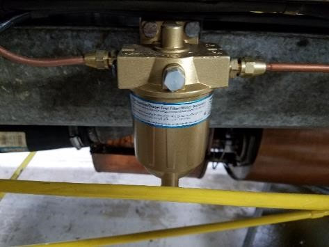 Update 8-17: the main fuel system has performed extremely well. For some reason, I have been draining a lot of water from the main fuel system and the filter will likely need replaced already. I don’t think it was as crucial for the pilot fuel JRG means it originally came from Goulds. When assembling the bottom part, the system will bottom out when about three threads are showing. The assembly will be less than half a turn past where it needs to be. There is not a lot off travel and there is a lot of tension on the spring 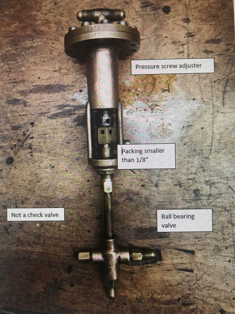 Exhaust System.. The initial system had big gaps from where the engine pushed it out before the engine steam intake was shortened. Welded the system closed to where the steam discharge pipe came in. I’m puzzled with the pipe. It is simply soldered together and seems to hold fine Tailpipe. I had soldered the tailpipe in the past/ it did not hold so I ended up welding it (TIG with High Silicon Brass rod from mcmaster) Pilot Light. Bottom unit was a Propane setup. I converted it back to Hexane. Pilot body by Don Bourdon 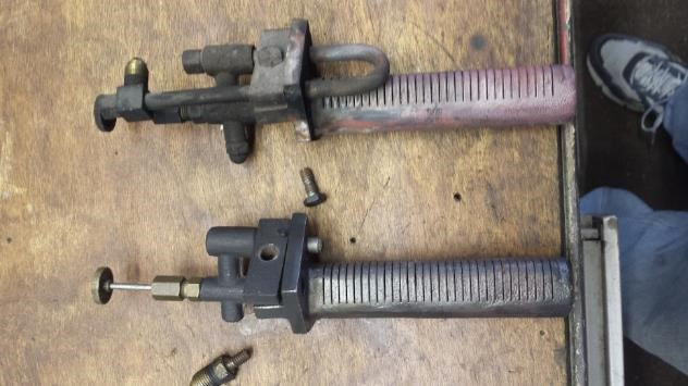 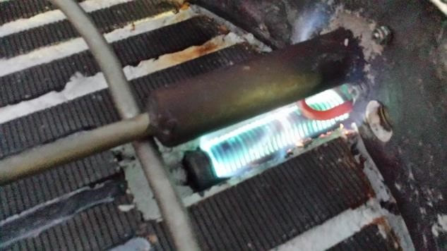 Built a new needle from 1/8 steel rod using lathe grinder. Threaded it to standard #6 and threaded the casting accordingly. It needs to stick out past the seat as it guides gasses into the casting. It is easily bent on removal 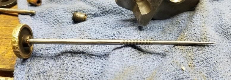 Sight glass (Gauge glass). An extremely useful study source is the klinger product catalogue at http://www.klinger.kfc.at/index.php/en/component/jdownloads/send/3-product-catalogues/19-product-catalogue-gauge-glasses The unit on the steamer is as size 1B reflex gauge and can be found at mc master at https://www.mcmaster.com/#gauge-glass/=1cljafz The following came from Pat Ferrell in Washington state after a facebook inquiry: I do use the McMaster reflex gauge gaskets, as they are a good value and they fit well. I use an antisieze on my gauge's bolt threads and I torque them starting from the center bolts like torquing a car's head gasket. Tighten a little at a time. I torque them when the gauge is cold, and then I re-torque them after the gauge has been fired and has cooled down again. I re-torque them every spring as an annual service. How many pounds? I torque them firmly, as I don't use a torque wrench, I don't want to guess the torque. In the 33 years of steaming, I have never had the quality of a reflex gauge glass degrade from use. Through the years I have lost about 3 gauge glass gaskets while on the road. I always carry spares with me. 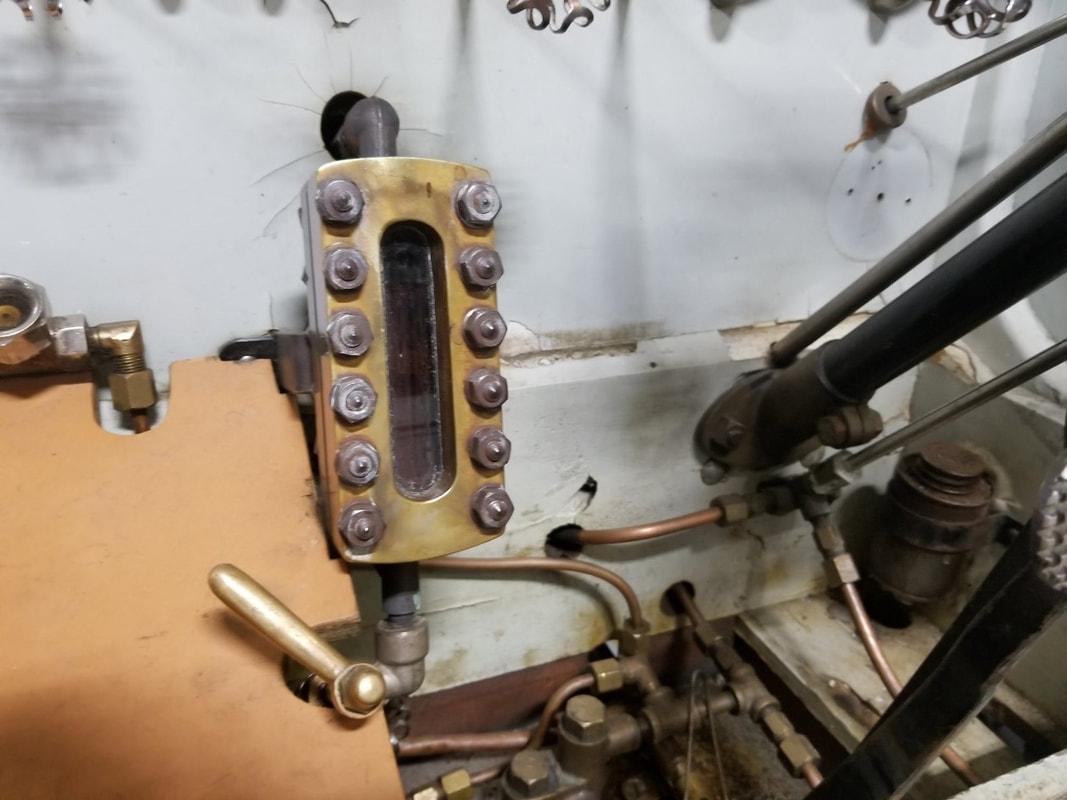 Burner (Baker Style. Made by Blazik) Remove and install: the burner will not come out with the car at its normal level. Lift the body and install two pieces of 2x4 to keep it up. A long enough piece of plywood held up in two spots will help finesse the thing out of the car but is indispensable to tweak it back in Disconnect the steering bar to give more room 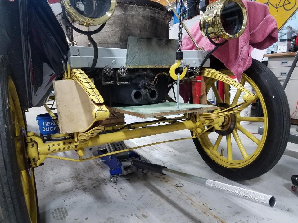 Burner make-up. The burner sits in an insulated pan. The easiest way to take the burner assembly out of the pan and put it back in is by doing it upside down. The gas diffuser is simple but the pipes are above the pan. If the pilot goes out and raw kerosene is blown in, there is no way for it to leave other than by burning it off. I used muffler repair dope to seal the halves together and furnace cement to seal up everything else Use masking tape to cover the slits and protect them from cement. Use insulation between pilot and burner “Imperial hi-temp stove and furnace cement, Grey” seems easy to work with Everything is screwed together with #10 button heads 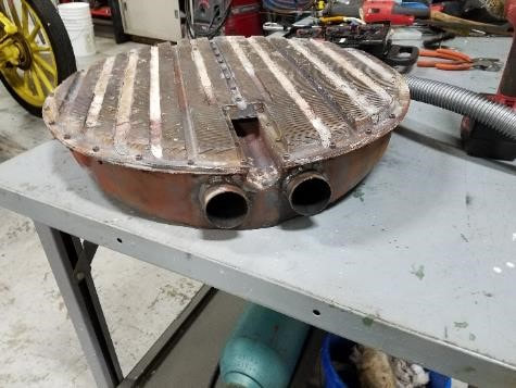 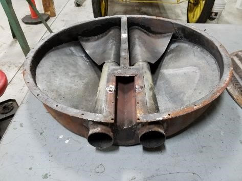 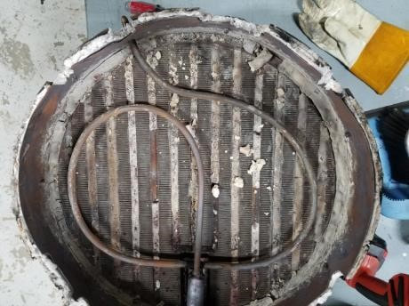 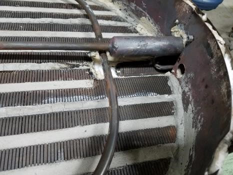 Hubcap. lost a hubcap in Iowa, decided to make a new one from ultra machinable brass from mc master 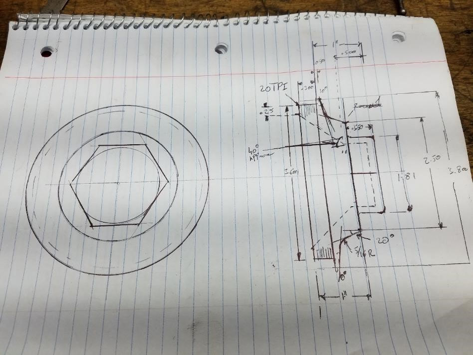 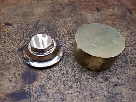 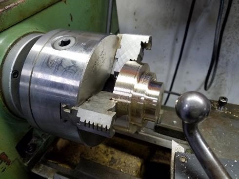  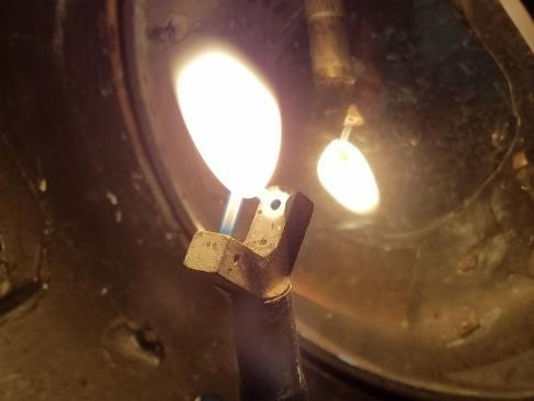
0 Comments
Brakes (Front). Front brakes are Tokico A1 2-pod systems. They were used on a number of Kawasaki and suzuki 500 models in the 90’s. Seals are skf 22441 (3.25”X2.25”) 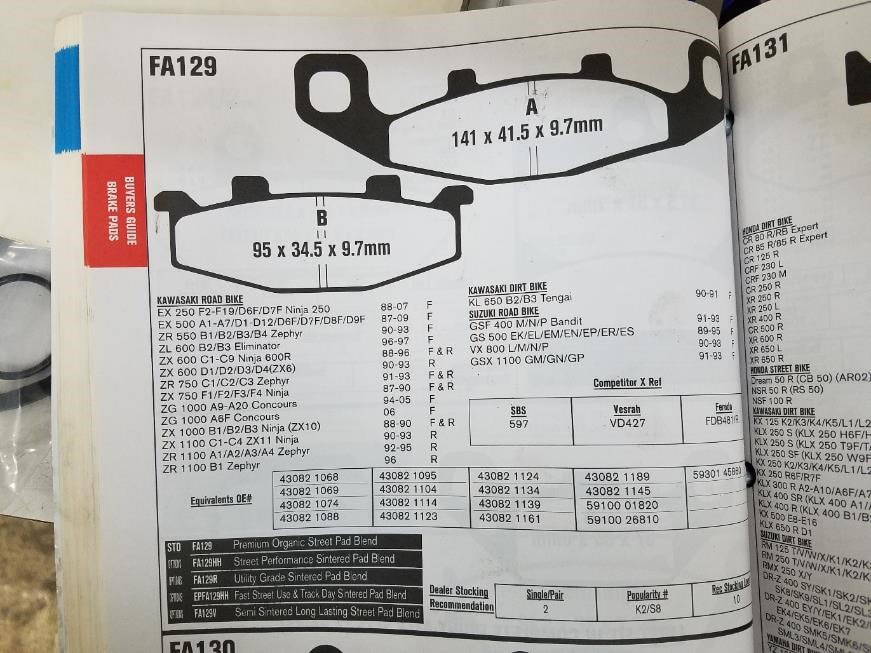 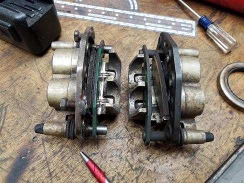 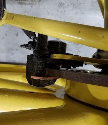 Brakes (rear). The outside brake is for parking and emergencies. As you pull the handle, it will get tighter and you may have to stop completely before it releases. The wheel can be removed with everything in place but you will need a wheel puller. Adjustment is done through the large yellow screw in the back (Pic Below) and the adjustment barrel is standard tread so to tighten, you have to push the ears up on the driver-side and down on the passenger side. A grease seal was installed in 2018 to try and keep oil off the Brake shoes 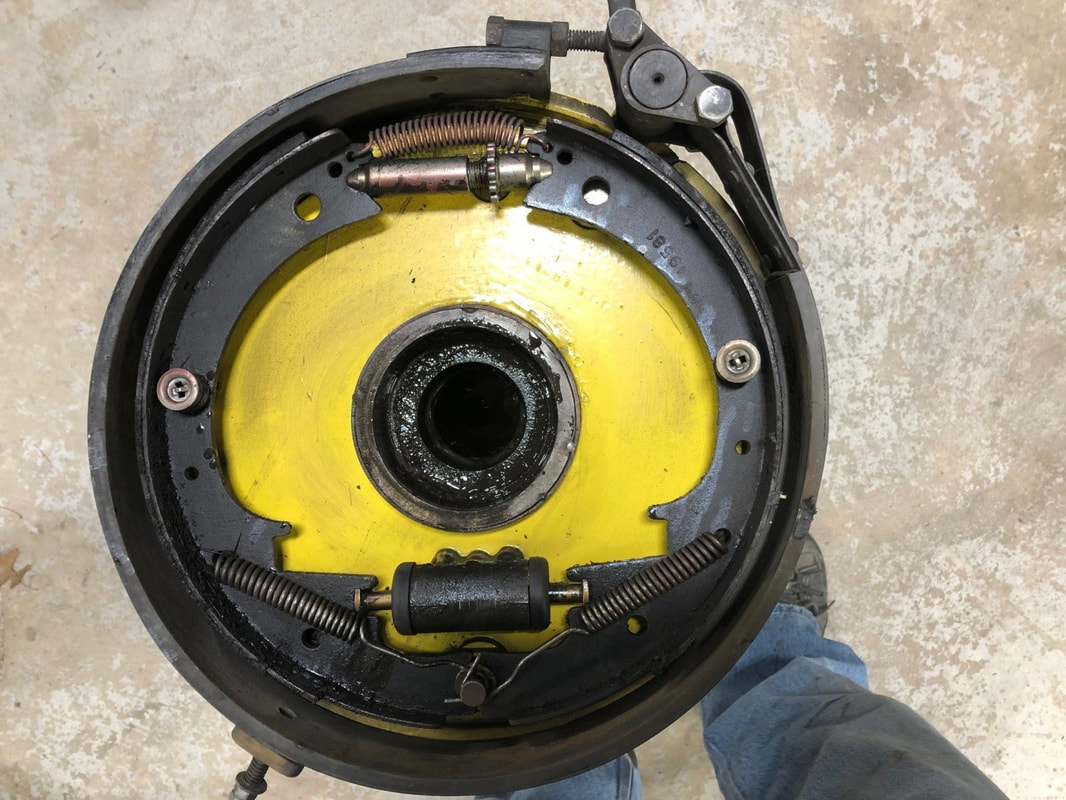 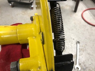 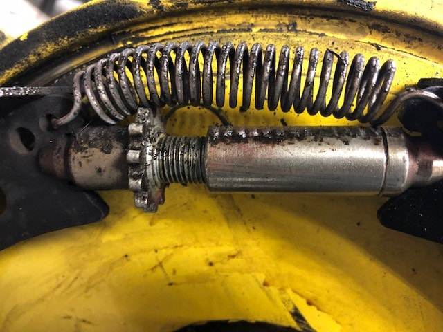 Tires. Contrary to what I thought, Tire and Tube repair on this car is not likely something that can easily be done on the side of the road 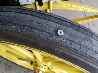 In August 2017, I ran over a screw with the front wheel. It was on the last day of the Vermont tour and the tire did not go flat until the next morning. After eighteen years of use, the tire had very little tread left so it was time for replacement anyway. Once Home, I removed the tire but was unable to get the new one on. The design calls for the inside part of the tire to be seated on the edge of the rim before the valve can go in. there is very little clearance between the tire and the three-piece rim so putting the tire on at an angle, allowing the tube stem to go in, is out. Eventually, Dave Vaughn put the tire back on the rim but in the process, ripped the new innertube. Also, between Dave and especially myself manhandling the tire and the rim, we did a lot of damage to the paint on the wheel. As the inner- tube needed to come out again, it was a good opportunity to rethink tire management basics Tire size: 36X4 Pressure: 60PSI min Vendor: Universal Tire Wheel: all with steel three-piece Rim Tire replacement consists of some major steps
Tire removal I have found it easier to keep the wheel on the car for this Remove the valve stem Mount the clamps on the tire and push the outside of the tire in enough to allow the outer rim to come off. 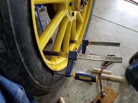 Remove the set screw on the rim lever and loosen the nut As gently as possible, remove the outer rim. If the tires have been on the car for a long time, “gently” will include a prybar and the rim will get distorted If the tire has been on the car a long time and has dried out, it may be possible to evenly slide it of the rim. If that is the case, push the valve into the rim before removing the tire. Next, see if you can move the tire off by hand. Even when using the clamps, try to remove them every so often and use your hands. This is an extremely tedious process that will see no more that around 1/16” progress per revolution. place your clamps to push the tire off the rim and start pushing the tire off the rim 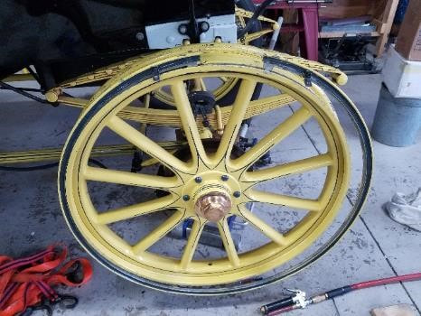 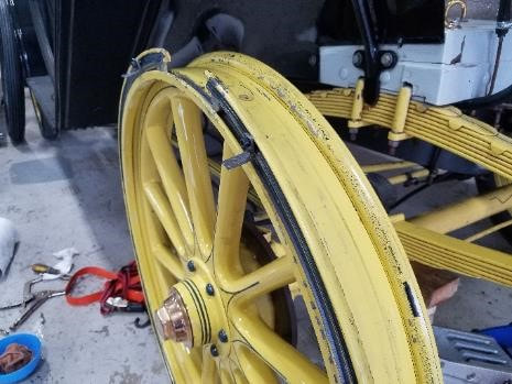 The rim is a Three-piece design. Loosening the little screw and tilting the lever outwards allows the rim to come off… in theory. In the model R, the wheels had not been touched since the car was built and the rim was rusted stuck in the groove. It took a substantial amount of effort to get it out and the rim elongated 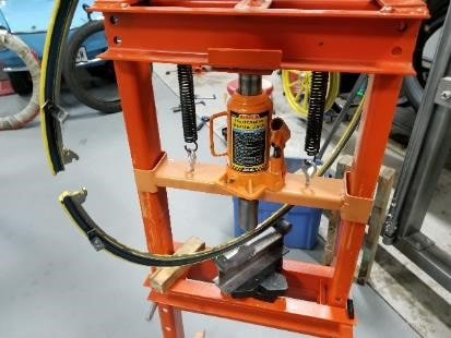 After cleaning the outer rim and the channel in the main rim, I marked bent-up areas and built a jig for the press to help get it back in shape. It takes only small amounts of travel to get the rim to bend and requires frequent fitting . I ended up drilling and tapping two holes in the rim (10-24 hardened bolts) (5/32 drill and 10-24 tap) and connecting two L-brackets and subsequently pulling the parts together with a ¼ threaded rod (Use a thick nut) after liberally coating the groove with never-seize 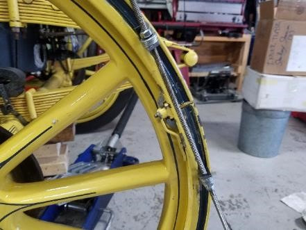 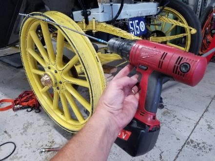 Mounting the tire. DO NOT INSERT THE INNER TUBE Slide the tire over the rim as far as possible. Use the tire-me-bob and a mallet to pound the inside on the rim past the first lip. You can then put the outer tire on and pound the entire blessed thing in. use the clamps to help. Progress will be tedious and, unfortunately, you will chip paint Continue until the tire covers the valve hole 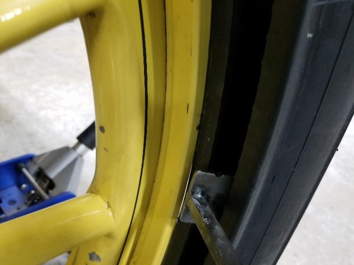 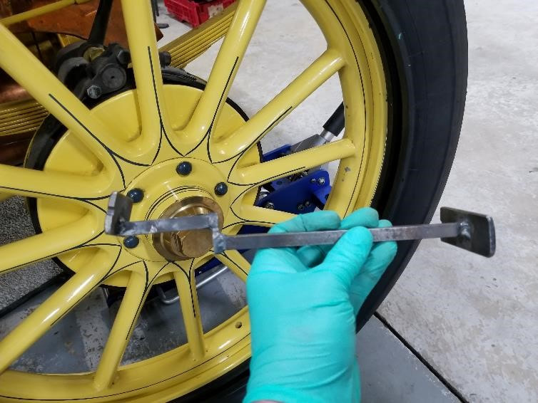 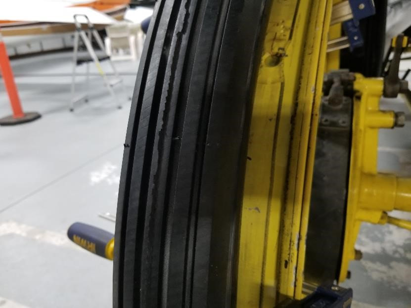 At this point, install the rim. You can leave the pulling mechanism on it. Inflate the tire with a rubber-tipped air chuck until it seats on the interior part of the rim. As the outer rim is lubed well, you may be able to work it out with a large screwdriver, pushing the tire in enough in the process without distorting the rim Put reverse rolled duct tape in the groove where the rim fits through so that no air can escape Blow up the tire with the airchuck until the outside tire pops off Place the inner tube as outlined in the next section Inner tube replacement. Remove rim as described earlier. DO NOT REMOVE THE ENTIRE TIRE if you can avoid to do so Clean, reshape and refit the outer rim If you’re only replacing the inner tube or if the tire is stuck, take the valve from the tube and use an air gun to blow up the inner tube and allow it to push the outside of the tire off the rim. Even if the inner tube has a very large hole in it, this will work 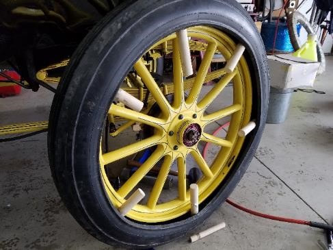 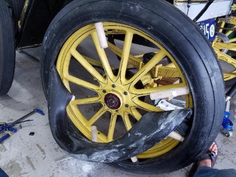 Place the 1 1/4” dowels between the rim and the tire. Push out the valve stem. It is a rubber stem and is a press-fit. Remove the inner-tube, working around the dowels. If you are only replacing the inner tube, don’t remove the rest of the tire Use baby powder Once the tube is in place, again inflate it to allow the tire to fit back over the outer rim, then pop it over the inner lip with screw-able wood vises as shown. Use of a hammer and dowel will help getting the area in between the wood vises to comply. There is extremely little wiggle room once the tire is on. Push the tire in far enough in so the outer rim will go back on. Replace the outer rim and gently blow the inner-tube to set the tire on the rim. Replace the valve and blow the tube to at least 60PSI Keep a little air in the tube while pounding the tire back on the rim to avoid getting it pinched between the tire and the rim Roof. After return from Maine in 2017, we noticed the front bow had snapped in two. On inspection, the wood appeared to be quite brittle but I felt a suitable repair repair would be to drill a ½” hole in both ends and insert a ½” tube into the holes, putting it together that way. It should be structurally sound and undetectable as it’s covered up well 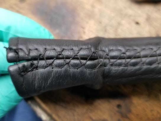 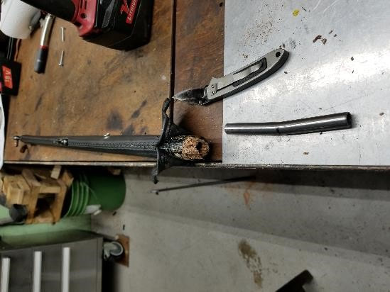 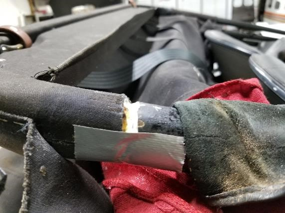 Engine removal 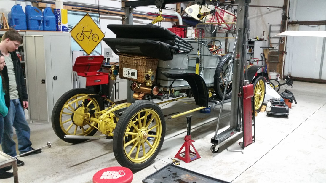 The easiest way to remove the engine is to do so with the rear axles attached. Remove the drip valve from the engine, screw in a ½” npt pipe around 6” long. the one in the box has a solid insert for added strength. It will support the engine on a floor jack Place the lifting strap under the body but on top of the exhaust pipe. Connect to the hoists and remove all slack I took the springs off with the axles this time as they had sagged and needed removed. If this is needed again, I would likely leave them on the car Remove brake lines, pump rod, exhaust and the steam line at the coupler Remove pitch pole nuts. They are mounted on a threaded rod and one of them did not go back on well Place the rolling floor jack under the pipe you threaded in and keep the handle under the differential lift until a slack is removed Unbolt engine from front strap and pull strap of the engine Lift the body until there is a gap between the spring and the axle and roll out the entire assembly Reinstall Reassembly is easier if you put the wheels on lock jacks to help manipulate the assembly 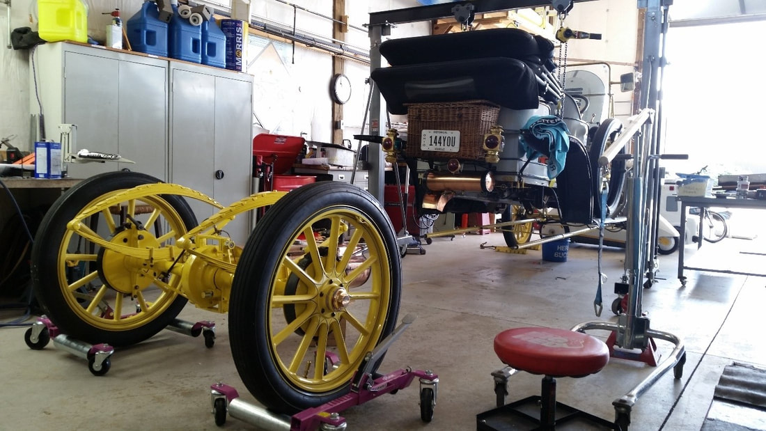 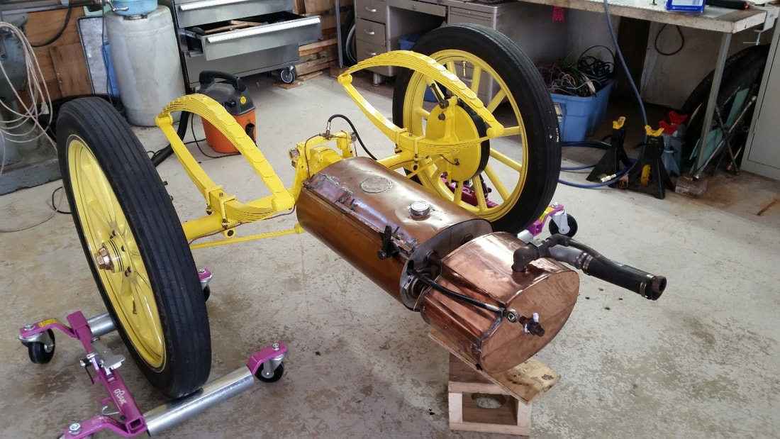 |
Archives
December 2022
Categories
All
|

 RSS Feed