|
Steam Car Network
|
|
(SACA Board member Tim Nye, learning that I was planning a visit to the University of Michigan’s Buhr Shelving Facility, asked me to scan the following article. It is an English translation of a Czech article, right at the end of WW2. It is fascinating in that the Czech engineers were running a stationary steam engine without cylinder lubrication, instead using carbon rings to seal the cylinders. Ed.) HIGH SPEED STEAM ENGINE WITHOUT LUBRICATION By H. Frank and J. Rais. (From VDI Seitschrift, Vol. 89, Nos. 5/6, February 3rd, 1945, pp.6466). (Translation appearing in The Engineer’s Digest, October, 1945 Vol. 2, No. 10.) A STEAM Engine to operate without cylinder lubrication has been designed and built by the Skoda Works (Czechoslovakia – Ed.) for a special purpose, where oil-free exhaust steam and highest economy at even partial loads are vital requirements. The engine was built for an output of 440 h.p., with live steam of 43 kg. per sq. cm. pressure and 380 deg. C. temperature, the back pressure being 7-9 kg. per sq.cm. (steam at 612 lbs. per sq. inch, 716 degrees F and 100-128 psi back pressure. This engine was briefly mentioned by Stan Jakuba in the April/May/June 2000 issue of the Bulletin. He noted it had a water rate of 18.3 pounds per horsepower-hour. This poor water rate is undoubtedly due to the low expansion ratio responsible for the high back pressure. It’s almost certain this industrial engine was designed to produce a high back pressure so that the exhaust steam could be used in other industrial processes. Ed.) Aiming to secure oil-free exhaust from a reciprocator, the Skoda Works had carried out extensive experiments with regard to the use of carbon seals. However, these experiments, conducted since 1935, had been confined to considerably lower pressures. Thus, when faced with the present task, a new approach to the problem had to be made. The new series of tests were concerned with finding the most suitable type of carbon material, most suitable, that is, with regard to mechanical strength, thermal expansion, wear, and ability to withstand high operating temperatures. The most suitable material for the piston and the piston rod had also to be ascertained. Furthermore, an existing engine was equipped with carbon seals in order to measure leakage and other data. Carbon is adversely affected by the presence of oil, a sticky mass being formed which exerts an abrasive action upon the piston rings and wears them down with great rapidity. Particular attention had therefore to be paid to preventing lubricating oil from the crank case, from reaching the carbon seals. In this respect the provision of duplex scraper rings with inter-drainage proved most helpful. These rings are now made of sintered iron in place of bronze, as hitherto used. (This section can be interpreted to mean that the piston was affixed to a piston rod which, in turn, was reciprocated by a crosshead. It’s impossible to speculate on whether it was single or In this manner the crankshaft, connecting rod and crosshead could all be oil lubricated without fear of introducing oil to the carbon rings. Since the piston has no appreciable side loads, likely not even contacting the cylinder wall, no lubrication would be required for anything but the piston rings. Ed.) Carbon is a very good material for sealing purposes and by no means inferior to a metallic seal provided the rubbing parts to be sealed are as hard as possible and have a mirror-type surface finish. Should this not be the case, carbon particles will lodge in any existing pores and wear of the carbon rings will be inevitable. A horizontal engine design had to be ruled out for reasons of cost, and a vertical design had therefore to be resorted to. A multi-cylinder design had to be chosen, since large size carbon seals are net feasible because of danger of breakage. It was, moreover, necessary to decide upon a single-acting engine type in order to eliminate the stuffing boxes. The specified engine output called for a six-cylinder design with a bore of 199 mm. and a stroke of 200 mm., the engine speed being 750 r.p.m. This results in a mean piston speed of 5 m. per second, which is a high value hitherto rarely used in steam reciprocator practice. (bore of 7.835 inches, stroke of 7.874 inches at a speed of 984 feet per minute, similar to that of some Doble engines – Ed.) 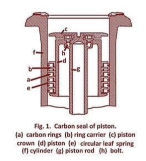 (The magazine illustrations weren’t sometimes too clear. The magazine was almost 70 years old and it’s possible that British wartime rationing didn’t help as regards paper and ink quality. The drawings have been either modified or replaced as possible. Absolute reliance on the images should not be taken as they are best interpretation. Ed.) Upon removal of the cylinder head, the carbon rings (a), as shown in Fig. 1, are slipped over the piston (d) together with the ring carriers (b). Circular leaf springs (e) serve to press the carbon rings lightly against the wall (f) of the cylinder. The piston crown is connected with the piston rod by means of the bolts (h). As these bolts exhibited fissures after short time in service, they were subsequently replaced by longer ones. The method employed for sealing the valve spindles is outlined in Fig. 2. Here it will be seen that the carbon bush (b) serves both as guide for the spindle (a) and as first stage gland, the steam pressure being throttled to a certain extent by the labyrinth-action of the grooves provided in the carbon bush. Sealing of this carbon bush against the valve body is effected at top and bottom of the bush by means of the elastic copper packings (c), the required degree of compression being exerted by the threaded gland (d). 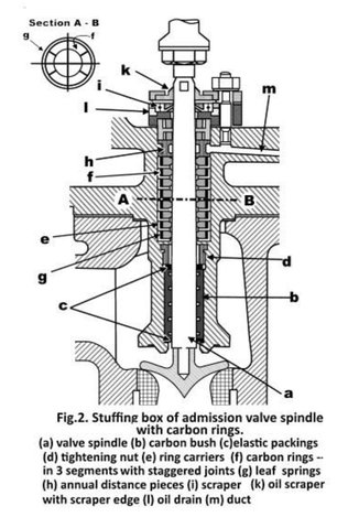 The stuffing box proper is constituted by the ring carriers (e)containing the carbon rings (f). Each of the latter is composed of three circular segments, the segments of adjacent rings being staggered by 60 deg. (Detailed section A-B in Fig. 2). The carbon segments are pressed against the valve spindle by means of the insular leaf springs (g). Furthermore, locating pins are provided to keep the carbon segments from rotating. In order to prevent the leakage of steam to atmosphere, distance piece (h) is inserted below the two topmost rings, this annular distance piece connecting with the back-pressure steam space by means of the duct (m). The two topmost carbon rings therefore act only as seals against the back pressure of the engine. In this way steam loss is kept to a minimum. The rings (i) and (k) act as oil wipers, with the leakage oil being led away through the opening (l). The mutual angular disposition of the six cranks of the engine crankshaft is indicated in Fig. 3. The connecting rods are forged and milled in order to keep their weight to a minimum. The big end bearings are made in cast steel halves, while the crosshead bearings are of the box type. The light metal crossheads have wrist pins of special bronze. The crank case is a single welded piece in order to avoid bolting the crank shaft bearings; the latter are bolted to pedestals enabling the withdrawal of the crankshaft to one side without lifting it. The cylindrical crosshead guides are made in halves and can be easily removed together with the crossheads through the openings provided in the engine casing. In the original engine the piston rods and certain other parts were made of stainless steel, but this precaution was later found to be unnecessary. 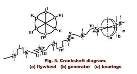 The employment of a mechanical governor had to be ruled out because of the high engine speed and the large controlling forces required, and a pressure oil governor system was therefore adopted, as shown in Fig. 4. The pressure oil pump as well as the gear type lubricating oil pump are driven from the engine shaft. Referring to Fig. 4 it will be seen that the small fly-ball governor (b) acts upon the pilot valve (c) of the slave cylinder (d). Valve control is effected in a novel manner, there being a cut-off control lay-shaft in addition to the main lay-shaft. The admission valves (e) are controlled by the cams (g) and the exhaust valves by the cams (h). The main lay-shaft revolves at constant speed, while the angular position of the cut-off layshaft relative to the main lay-shaft can be adjusted by shifting the pinion (i) by the movement of the piston of slave cylinder (c). Electrical remote engine speed control is provided. The engine is equipped with lubricating oil and pressure oil coolers, oil filters, and an emergency governor with oil hydraulic operation of the throttle valve. A manually operated pressure oil pump to set up the required oil pressure for starting is also provided. Provision for the absorption of thermal expansion is made at all vital points, including the steam piping. 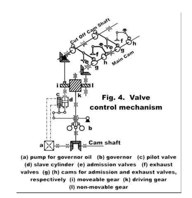 The steam supply line from the boiler was laid out with a minimum of bends, a distributing header being provided close to the cylinders. From observations made at points of the live steam connections close to the admission valves, it was found that there prevailed a weak steam oscillation of a frequency corresponding to the rotational speed of the engine. In addition to this, higher harmonics and a certain amount of non-harmonics were also found to prevail. The most suitable means for the suppression of these oscillations has not been found as yet. As the compression amounts to about two-thirds of the admission pressure, there also occurred a small amount of vibration of the admission valves, but this could be eliminated by changing the valve springs. Compared to a slow speed poppet-valve engine of equal power at 125 r.p.m., the present engine affords a saving in weight of some 60 per cent. At the end of August,1944, the engine had been in service for about 8,000 hours without showing any marked wear of the carbon rings. The amount of cylinder lubricating oil saved during this period amounts to more than 5,000 kg. The guaranteed specific steam consumption was 11.2 kg. per kW.-hr. (18.4 lbs. per h.p.-hr. - Ed.) with a tolerance of +5 per cent, with a load of 410 h.p. This compares with a measured consumption of 11.95 kg. per kW. hr.,(19.6 lbs. per h.p.-hr. – Ed.) that is, +6.7 per cent in excess of the guaranteed consumption. From diagrams taken at a later date, it was, however, found that two cylinders showed insufficient compression owing to faulty adjustment of the valve control. It is therefore confidently expected that after proper adjustment has been made the guaranteed steam rate will be met without tolerance. The indicator diagrams reproduced in Figs. 5 and 6 were taken with an electrical indicator. They clearly show the resonant oscillations occurring during the admission period. 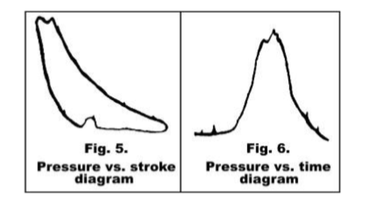 (A couple of notes seem worth mention. It mentions that the cylinder walls should be quite hard and as smooth as possible. This seems reasonable as graphite is soft and would wear away against an even mildly abrasive surface. Industrial hard chrome (not the stuff put on cars and motorcycles for the sake of being shiny) sounds like it might fit the bill, if polished. To be clear, this would be the kind of chrome plated onto injection molds to reduce wear … and other such heavy-duty work. Hopefully the article has been of interest. It would seem to follow that, if this approach worked on engine cylinders, it might also be valid for piston valves. It becomes more debatable for slide valves given the pressure applied to the sealing surfaces. After having slaved over a hot keyboard to put the article into a computer, and reworking some drawings, Tim Nye pointed out that that I had missed the fact that Josef Rais, one of the authors, had previously taken out patents on carbon piston rings and seal. The US patent, which is probably the most easily accessed, was applied for in March of 1934 (originally April 21, 1933 in Czechoslovakia) and was granted on April 4, 1939. It carries the title “Packing Ring for Sealing the Pistons and Piston Rods and was assigned to the Skoda Works in Pilsen, Prague, Czechoslovakia. I have to thank Tim for this observation, it brings the article into much clearer focus. Rais makes the case for his patent, as follows: “This invention relates to a new and improved type of packing ring for sealing the pistons and piston rods of reciprocating engines and machines using working cylinders and reciprocating pistons. The known constructions of engines and machines of this type suffer from the disadvantage that the packing members must of necessity be lubricated with some special lubricant supplied from without. This requirement results in a considerable increase in the cost of running, and expensive means are necessary for reducing the quantity of lubricating oiI to the minimum. In steam engines, the lubricating oil contaminates the exhaust steam, so that the latter cans not be used for certain purposes, since it contains excessively large quantities of oil. In the case of compressors, the lubricating oil can be caused to ignite. In consequence of the increased air temperature, thereby resulting in an explosion and hence the destruction of the entire machine. (When working with 5,000 psi air compressors, while in the Navy, we used special vegetable based oils for cylinder lubrication specifically to avoid these explosions. Ed.) Furthermore, the coolers are apt to become fouled by the lubricating oil, so that a special oil eliminating device becomes necessary. In the case of compressors in which a lubricant other than oil is employed, the pistons must be provided with soft packing means, for example cups, which are, however, comparatively short lived. In the case of refrigerating machines also, the lubrication with oil, glycerine, and other lubricants often gives rise to troublesome disturbances. Similar inconveniences due to the necessity for lubrication occur in the case of internal combustion engines also. The present invention overcomes these drawbacks by virtue of the arrangement that the packing members of the pistons or piston rods, or of both, consist of rings of carbon, graphite, or similar frictionless self-lubricating material, which rings are so resiliently mounted relatively to spring metallic supporting or holding means, that the necessary radial resiliency is provided without any independent lubrication whatever. These carbon rings are inserted in metal holding bushes, both the ring of self-lubricating matter's and also the resilient metal holding means being cut through by a single cut, for the purpose of enabling the entire packing member to be resilient radially. The packing ring according to the invention is rendered particularly well able to withstand the strains and stresses to which it is subjected by virtue of the arrangement that the ring consists of two coaxial independent rings loosely mounted one upon the other.” Rais notes: “In the hitherto known constructions of packing rings of carbon, graphite, or similar material the ring is either divided into a plurality of segments or else is rigidly connected to a metallic base. The first mentioned principle of construction does not ensure a perfect seal nor a uniform pressure of the packing ring against the co-operating surface, whereas with the second principle of construction the Independent stressing of the carbon packing ring is prevented, and in addition detrimental stresses are transmitted from the underlying base to the carbon ring whereby either the connection between the carbon ring and the metallic underlying base or else the carbon ring itself is damaged. These disadvantages are overcome by the present invention, by virtue of the arrangement that the metallic ring is loosely inserted in the carbon ring, with possible locking against lateral displacement. In accordance with the invention, the packing ring may for this purpose consist of two coaxial and independent rings loosely mounted one upon the other. These two rings are mounted one upon the other without any rigid interconnection whatever, with the result that the resilient action of the metallic ring is uniformly transmitted to the carbon packing ring. The sealing action of a packing ring constructed in accordance with the invention can be increased or reduced as required in the various cases of utilizing the rings in machines by choosing suitable metallic resilient material for the production of the resilient metallic ring. The seating surface between the two rings can be cylindrical; but may with advantage be provided with one or more grooves of any desired cone figuration for the purpose of preventing axial displacement. Packing rings constructed in this manner permit of radial movement of the ring performing the packing function. In this case, however, if the grooves be of dovetail or other shape, it is necessary to provide such connection between carbon ring and metallic ring with an amount of play which admits of displacement within limits permitting of perfectly uniform resilience of the packing ring. The resilient packing ring according to the invention is cut through in a normal manner at one point on its periphery, the cut in the packing ring and that in the metallic ring but either coincident or in offset relation to each other.” The following illustrations are all derived from the patent, while the abbreviations in the table replace the number designations used to describe patent features (on the theory that it might be easier to remember MR stands for “metallic ring” rather than the number 13, or whatever). 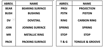 Figure1 shows three rings installed in the piston while Fig. 2 describes the rings themselves. 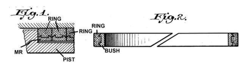 Figures 3 through 8 show a number of variations on the piston ring, these differing in the manner used to locate the carbon ring inside the metal ring; with Fig. 3 having no mechanical retention whatsoever other than contact with adjoining rings or piston grooves. 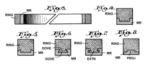 Figures 9 and 10 consist of packing assemblies holding multiple carbon rings. 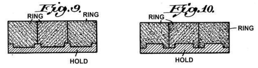 Figures 11 through 13 show pistons built up in segments, which serve to entrap the packing elements. The bushings are either a springy retainer or are backed by leaf or helical springs. The stops distribute the spring load against the bearing surface after the carbon rings have reached the worn in state. Thus, the springs are actually a temporary expedient used to break in the packing element. 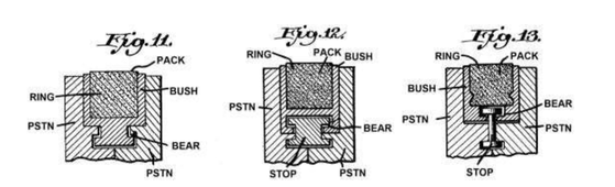 Figs. 14, 15, 17 and 18 also show sections of modified forms of packing rings inlaid in the material of the shell of the piston. Fig. 15 is a plan view of Fig. 14, and Fig. 18 a plan view of Fig. 17. In both instances, the split halves of the bushings connect with a tongue and groove to provide tighter joints. 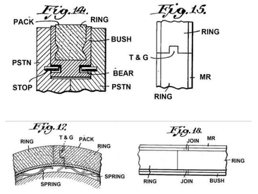 Generally speaking, the above embodiments are used with split, built-up pistons. Figures 21 and 22 are designed to be installed into the groove of a solid piston. Leaf springs underneath force the carbon ring against the cylinder walls while the stops are pins driven into holes drilled into the piston grooves from either the top or bottom of the piston. The rings are made in halves and use tongue and groove joints to promote tightness. 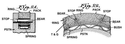 Rais noted: “In accordance with the invention the packing ring may be constructed in such a manner that its resiliency in a radial sense is effected by metallic means provided beneath the ring.” This implies that he understood the metallic ring would supply the resiliency required to hold the carbon packing in contact with the sealing surface but did not rule out the natural resiliency of the graphite itself. Today, we might have a greater range of options. At least two companies manufacture carbon materials engineered with an array of properties. Graphitar products are manufactured by US Graphite in Saginaw, Michigan while Superior Graphite is headquartered in Chicago, Illinois. Superior Graphite has been in business since 1917 while US Graphite was a spinoff of the Wickes lumber business and was founded in 1895 to exploit then-recent graphite discoveries in Mexico. The following comes from the Superior Graphite website found at: http://graphitescarbons.superiorgraphite.com/Asset/RGC-Brochure.pdf 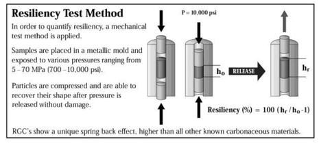 (RGC stands for ‘Resilient Graphitic Composites’, Ed.) 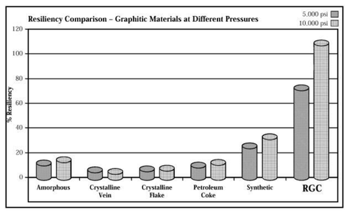 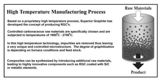 US Graphite sells what appear to be similar engineered graphite products under the tradename ‘Graphitar’. There are a wide variety of Graphitar products with specific properties for a range of applications. These can be molded directly to shape, or machined, whichever is advantageous. The company website shows their products being used for mechanical seal faces, as bearings (dry and water lubricated) and to form vanes, rotors and pump pistons. Perhaps some of these engineered carbon products have a place in modern steam automobile engineering.
Data sheets for their various products include such data as resilience, strength, hardness, porosity, temperature limits, PV factors, oxidation and chemical resistance can be found at: http://www.usggledco.co.uk/Resources. The Bulletin staff would enjoy any experiences you may share regarding carbonaceous materials as applied to steam engines.
2 Comments
John Archibald
1/4/2022 10:17:13 pm
Hi, You have some amazing technical details on how a modern stream engine can be made more efficient. So is there any applications of this modern technology working on cars or trucks? My interest is in developing the steam locomotive using poppet valves with high superheat at 600 psi inlet. Franklin USA and Caprotti in the UK had good results of these valves, but as you know the tide turned on steam R&D and now requires a lot more work to catch up to the current and future IC engine technology. 11/4/2022 08:05:17 am
Thanks so much for the explanation of how piston rings work based on the materials they're working with. My partner has been having trouble with their engine and they think it might be the rings. We've been looking into piston rings and what to know about them so we are sure to buy the right ones. Leave a Reply. |
Archives
December 2022
Categories
All
|
 RSS Feed