|
Steam Car Network
|
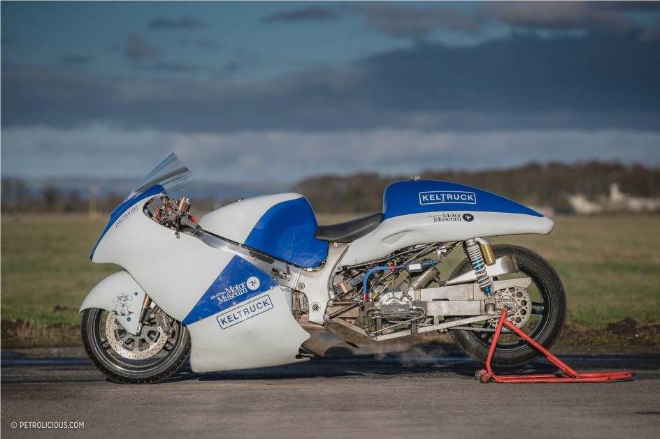 The Development of a Steam Powered Motorcycle PART ONE The following article covers the basic design philosophy for an attempt at the land speed record for a steam powered motorcycle and perhaps the outright record for any steam powered vehicle. As a starting place for a steam powered land speed record, a motorcycle is a terrible idea. The restricted space envelope and poor aero-dynamic characteristics make it the worst possible concept. However, not to be daunted that is what we chose. The decisive factor was because we had this small Bower and Bell engine, which was an Abner Doble inspired design, it is too small for a car, but deserved to be used in something. Our love of motorbikes and the idea of a steam powered motorbike is more appealing to us than the ultimate record itself, we have used a Suzuki Hayabusa as the donor vehicle. The basic formula pertaining to drag is: Drag = Cd x (1/2 x density of air x velocity2 x Area), where Cd is the co-efficient of drag and Area is the projected frontal area. As we can see, drag increases by the squared function of speed. The two most important factors that we can control in design space is frontal area and the Cd. A motorbike has a relatively small frontal area, which is good,. However, even fully faired racing motorbikes struggle to achieve better than a Cd of 0.6. This compares to 0.3 for a modern road car, a Streamliner can have Cd as low as 0.12.From the RSR Bonneville Aero-Horsepower & Drag Loss Calculator: available online at: - https://www.rbracing-rsr.com/aerohpcalc.html Coefficient of Drag: Street, faired motorcycles are notoriously inefficient aero-devices with Coefficient of Drag (Cd) figures in the 0.6 range. For example, a Suzuki Hayabusa has a Cd of .561 whereas a Kawasaki ZX-12 has a Cd of 0.603. Modern cars often have paid close attention to aerodynamics and may have Cd figures of 0.3. Streamliners may have Cd figures of under 0.2, perhaps as low as 0.15 or in some cases figures of 0.10 have been achieved. Frontal Area: Reducing frontal area is key to going fast as the horsepower requirements go up exponentially as you push that "barn door" through the air. You'll need a close approximation of your vehicle's frontal area in square feet to make this calculator entry. A Suzuki Hayabusa has a frontal area of 6.01 square feet. A Kawasaki ZX-12 has a frontal area of 6.09 square feet. Some streamliners like the Lambky Vincent have only 4 square feet frontal area. Vehicle Weight: On shorter courses with asphalt surfaces and good traction weight is more of an issue than it is at Bonneville, where weight can aid traction on the slippery salt surface. Short courses are more of a drag race and accelerating extra mass is not a good idea. At Bonneville the big dogs will be on the long course with over six miles of salt with the clocks at the 2, 4, and 6-mile markers, so weight is not nearly as much of an issue. 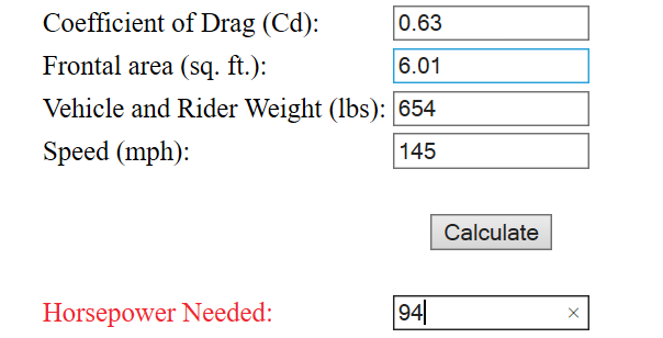 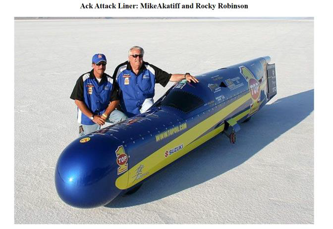 Figure 1: An example of a record setting Streamliner at Bonneville 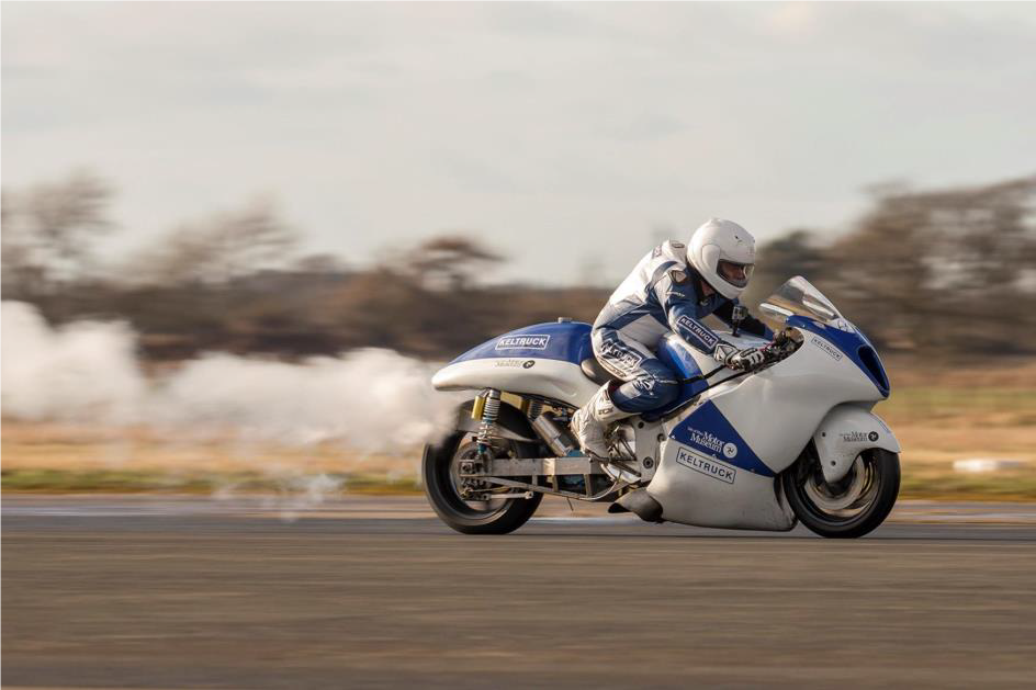 Figure 2: At Elvington airfield UK setting 80mph run Basic Design. The engine was chosen due to availability and suitability (mainly size). In some respects this is not an ideal engine for the task. However, it was suitable and most importantly available! The engine in question is a double acting Bower and Bell V twin, a modest 1.25 in diameter high pressure cylinder and 2.5-inch diameter Low pressure cylinder, the stroke is 1.5 inches with a fixed 50% cut-off. Various figures are bandied around for its power, approximately 30hp at 3000rpm with 1500psi has been quoted. One owner from Scotland who carried out trials with a Dynamometer, has stated that he achieved 22hp at 840psi and a constant 1890rpm. Calculations carried out indicate correlation with the reported test results from Scotland. Interestingly using the same calculator with the quoted 1500psi and 3000rpm show around 32Hp from the Hp cylinder only. Alternatively calculating for both cylinders (including subtracting the negative work from the HP cylinder on its exhaust stroke) shows ~29HP as a single acting engine, if allowing for double acting, then power is ~58Hp. We intend to push it as far as we can, using the spreadsheet I have created using 840psi, 1890rpm it predicts 20.8hp compared to the 22hp reported. At 3600 rpm, 2000psi and 900F, it predicts 94hp. I’m somewhat sceptical that the engine will produce this or indeed hold together. However, that is what we intend to trial on the Dyno. As far as the spreadsheet goes, it is quite complex and is not a simple pro-rata affair. When data from other verified engines is entered, it predicts values commensurate with those reported. So, until proven otherwise, we have to believe the numbers at this stage! The water and fuel usage are calculated at 743lb/hr of water and 8.96US-Gallon/hr of Kerosene at full power. The bike carries 53lb of water, enough for about 4 minutes running at full power. However, to go from a standing start to one mile only takes around 30 seconds, so this is ample for the purpose. Fuel has rather more in reserve, as fuel is consumed even when water isn’t, to maintain temperature and pressure, for example on the paddock stand before a run. In theory the engine should hold together, as it has been proven to be quite happy at 3600rpm. The small (0.75 inch) crank throw, means that piston velocity is no higher than other steam engines with longer throws and maximum torque is generated at low rpm. Therefore, if it doesn’t break at the start up, then there is no reason to believe it will fail at the high revs. However, since engine failure must be quite a credible possibility, the engine output shaft has been fitted with a bespoke free wheeling hub such that if the engine locks up, the rear wheel will remain free to rotate. See Figure 3 below 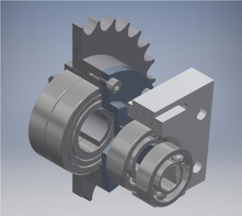 Figure 3:Sprag clutch freewheeling hub with water pump output shaft. A mechanical water pump is fitted to the end of the free-wheeling hub output shaft. This delivers all of the water necessary. The capacity of the water pump is approximately 200% of theoretical demand, ensuring the ability to rapidly increase the water level within the steam generator if steam temperature is too high. The water pump is driven by an eccentric, which can be changed to provide different water delivery, should testing reveal changes are required. Water must be added to the steam generator at start up by external means, as no electrical or hand pump is provided on the bike. We have chosen to run the steam generator at between 900 and 950 Fahrenheit. The steam lubricating oil limit is 1000F. This increase in temperature results in reduced water consumption for a given power. Abner Doble typically used 850lb/hr at 850F as the requirement for a 100Hp engine. This aligns with the water consumption predicted by my spreadsheet. Steam Generator The steam generator has been designed to output sufficient steam for 96Hp, which is 750lb/hr at 950F. The basis for all fluid velocities and required surface area has been calculated from the work of Abner Doble, including the required combustion volume. The steam generator has ~430 feet of 8mm OD tube for the water coils, 180 feet of 12mm OD tube for the steaming coils, 30 feet of ½ OD tube for the Normaliser and 30 feet of ½ OD tube for the super heater. The water and steaming coils are carbon steel for improved heat transfer properties. This minimizes the required tubing and the Normaliser and Superheater coils are 316L stainless steel to withstand the higher temperatures. The total weight of tubing is 120lbs and the internal volume is 0.3 cubic feet. If one considers that the required output of 727lb/hr equals 12lb/min and the internal volume is sufficient for ~9.5lb of water/steam, then simplistically the approximate time that a molecule of water entering at the inlet to the generator takes to subsequently exit the generator at 950F is (9.5/12) *60 = 47.5 seconds. At full power the velocity in the water tubes is 9ft/ sec, in the steaming coils 50ft/sec and in the superheater 75 ft/sec. Therefore, notionally the water spends 48 seconds in the water coils, 3.6 seconds in the steaming coils and 0.8 of a second in the superheater. This might seem incredibly fast. However, comparing to Abner Doble’s design for a 100Hp generator producing 850lb/hr of steam at 1000psi, (steam at this temperature and pressure has a density of ~1.39lb/cubic foot). Producing 850/3600 = 0.236lb/sec. The super heater and normaliser coils are 3/4inch OD, 9/16inch ID and 39 feet total length. The cross-sectional area is therefore 0.2485inch2. The volume in the superheater is (39*0.2485/144) = 0.0673feet3, so contains 1.39*0.0673 = 0.0936lbs of steam. Therefore, to produce 0.235lb per second, requires the superheater to be emptied 0.235/0.0936 = 2.5 times per second, 2.5 times 39 is 98 feet per second velocity! 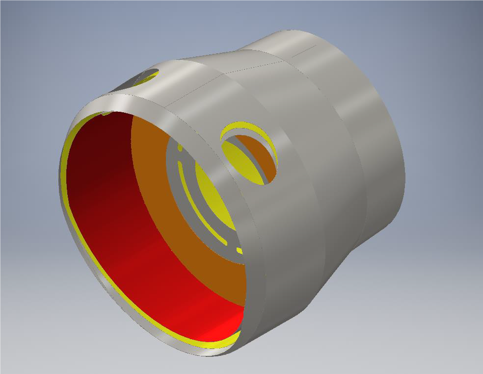 Figure 4: Steam generator casing For the generator controls we have a temperature sensor (referred to as TC1) at the end of the steaming coils, a Normaliser inlet at the start of the Normaliser coils for adding water to the top coils, should steam temperature be excessive. This is sized to allow for approximately 10% of feed water, followed by a pressure sensor (P1) and second temperature sensor (TC2) at the outlet from the generator. This follows broadly other successful control systems for monotube steam generators 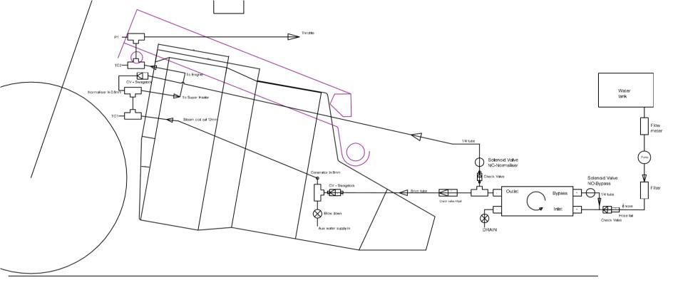 Figure 5: Schematic of plumbing At the steam chest on the engine, a third temperature sensor (TC3) and second pressure sensor (P2) is located. This is important for the generator control system as will be described later. The regulator is a fly by wire control. A suitably rated regulating stem needle valve is located between the generator and the bike engine. The twist grip throttle is in fact a potentiometer. This electrical signal is used via a controller to move a stepper motor, which actuates the valve. The controller is within a military spec case for protection and has its own Uninterruptable Power Supply (UPS). This consists of a stack of Super Capacitors, which charge as soon as power is connected to the bike. Should input signal or external power be lost, the controller automatically runs a valve close procedure, using the stored electrical energy within the Super Caps. The control and power cables to and from the stepper motor and control box, are run within an armoured sheath. As a back up to the regulator, a second valve is positioned upstream and is actuated by a hydraulic cylinder from the clutch lever. This ensures that the rider can manually shut of steam to the engine. However, once used, this valve can only be reset after all pressure is drained from the generator. The water pump has a pulsation damper fitted at the outlet and a relief valve set at 2300psi to protect the pump and damper. Between the water inlet to the generator and the water pump, are two check valves. Closest to the pump is a poppet check valve with polymeric seal. At the generator inlet is a metal seat lift check valve, rated for 3280psi at 900F. Immediately after the metal seat check valve is a relief valve set at 2500psi. Should the pressure exceed this within the generator, this will ensure the liquid content of the generator is immediately released, (albeit flashing of to steam in the process), therefore collapsing the pressure. The lower set water water-pump relief ensures that the mechanical pump can’t deliver water should the generator pressure be high enough to lift the generator relief. The main electrical power for the bike is provided by 3 in number 24v Lithium batteries each containing ~10Ahr. They can sustain a continuous discharge of 15 amps (each) with 70amps peak. At full load the fuel pump draws 8 amps, the air fan 20 amps, the control system 6 amps and the electrical boost pump (water suction delivery for mechanical pump) 3 amps. Total 37 amps. Burner The burner consists of a single flame tube containing an atomizing oil nozzle by DELAVAN. This is a Variflow nozzle that allows for modulation. 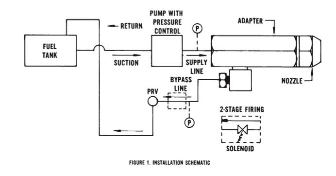 Figure 6: Burner schematic This system allows for a minimum firing rate of just over 1gal/hr, up-to a maximum of 9.9gal/hr> This is achieved via three control modes. At constant pressure (100psi) the bypass line is controlled via pulse width modulation (PWM) of a solenoid controlled PRV. This allows (with the nozzle we have selected) a firing range from 1.2 to 6 gal/hr. With the bypass line fully closed, fuel pressure can be increased (max 300psi) to give up-to 9.9gal/hr. This is achieved through PWM control of the fuel pump motor. Air is supplied via an Electric Ducted fan intended for radio-controlled aircraft. Again, through PWM, the air supply can be matched to the fuel delivery to give the correct air fuel ratio.  Figure 7: 3 phase 24V EDF Control System It should be stated at this point, that what has been described to date reflects the current status of the design. An earlier version of both the generator and control system have been physically trialled, and speeds of around 80mph achieved. This was very disappointing to ourselves, as we hoped to easily break the 100mph mark. However, subsequent investigations revealed that the generator was woefully under tubed, containing only enough tube for around 25hp, the burner could only deliver 3gal/hr. The piston rings were broken on the valve gear due to standing for a long time, such that the engine was severely compromised. With a fixed cut-off engine, it is extremely important that the generator can provide as much steam as is demanded, without the ability to reduce cut-off there is no ability to reduce steam consumption if pressure and temperature are low, this creates a vicious circle when it comes to monotube steam generators. The control and protection philosophy are as follows. The normal operational envelope is controlled via a small computer, vis a raspberry Pi, controlling fuel, water and air. 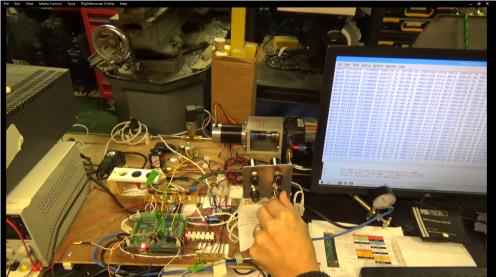 Figure 8: Test bed for Raspberry Pi control system If the system strays outside of the normal operational envelope, there exists a hard-wired relay-based protection system. This utilises industrial process temperature and pressure controllers, which hold the power relays made. Should protection limits be exceeded, power is removed from the relays, effectively shutting down the burner etc, regardless of what demand signals may be being sent by the control system. Should this hard-wired electrical system fail, then beyond this, we have physical mechanical pressure reliefs and an emergency steam shut of valve hydraulically operated via the clutch lever. A thumb kill-switch and a kill-cord are also provided, which have the effect of removing all power (shutting fuel solenoids etc). As previously described the regulator will then automatically shut upon loss of signal or external power. 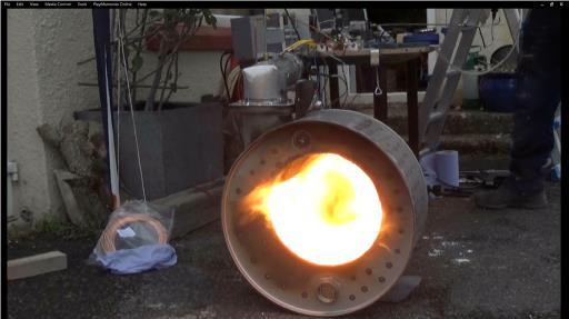 Figure 9: Dummy combustion chamber to trial control system Demand for fuel is calculated from the steam chest conditions. i.e. temperature and pressure within the steam chest determine steam density and thus the heat content of the volume of steam used. Steam density is calculated in real time by the PLC using a five-order polynomial equation I developed from steam tables. It is sufficiently accurate across the permissible operating range of pressures and temperatures that we are using. Swept volume, inlet cut off and rpm are then used to calculate mass flow rate of steam. 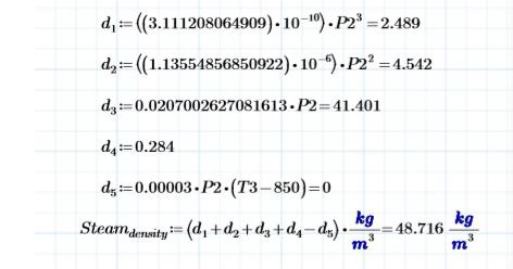 Figure 10: Formula for steam density used by PLC  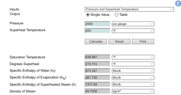 Figure 11: Actual values for steam at 850F and 2000psi from https://beta.spiraxsarco.com/resources-and-design-tools/steam-tables/superheated-steam-region#artical-top Steam Mass flow rate = Swept volume x cut off x rpm x steam density. Since inlet flow conditions and the effectiveness of the piston and valve rings will affect the real value, a multiplying factor is utilised. This can only be determined for a given engine via experiment and we have assigned this the notation leakage factor. From the pressure and temperature of the steam in the steam chest, the specific heat content can be calculated. Firstly, the saturated steam temperature is calculated using again a formula developed by ourselves, 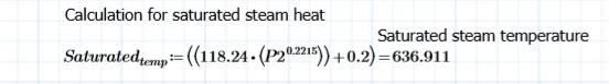 Figure 12: Formula for calculating Saturated steam temperature Using this the specific heat content of the saturated steam was derived initially using formula developed from the IAPWS Industrial Formulation 1997. Page 10 of 14 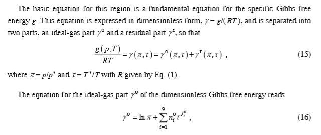 Figure 13: IAPWS Industrial Formulation 1997 for region 2. However, we have found that suitably accurate results for our region of operation can be achieved through the use of the following formula developed by ourselves. 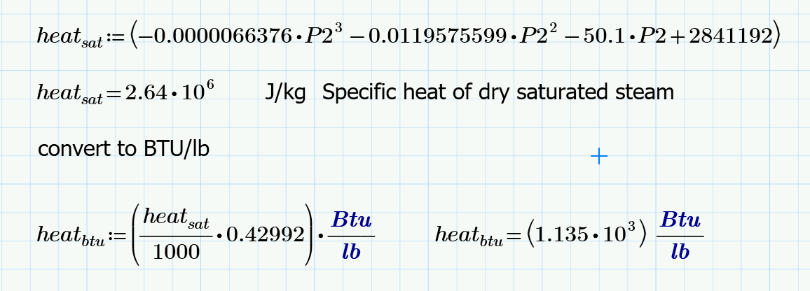 Figure 14: Formula for calculating specific heat of dry saturated steam Then the degrees of superheat above the saturation temperature are used to calculate the specific heat content due to superheat using a fourth equation developed. The sum of these values, is the total specific heat content of the steam being used by the engine. 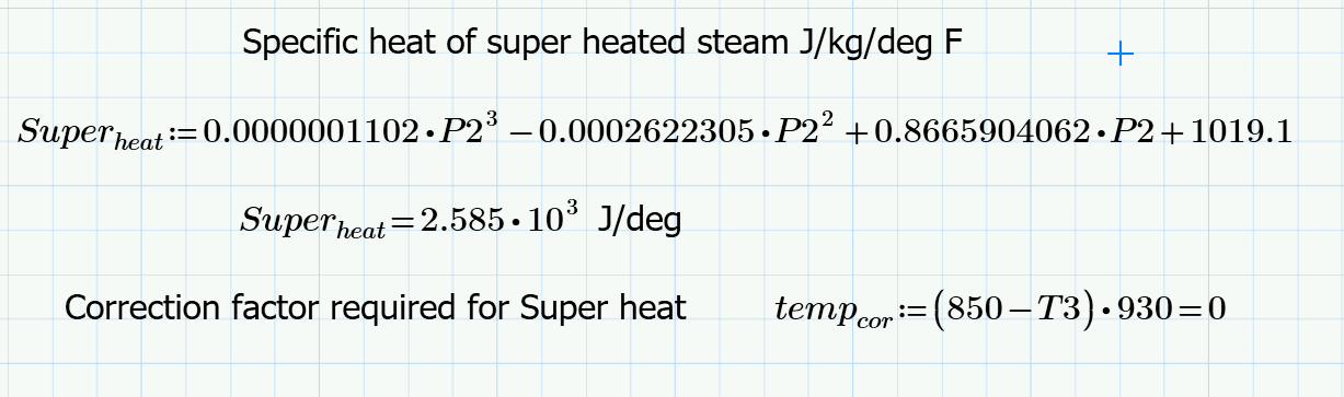 Figure 15: Formula for heat content due to superheat 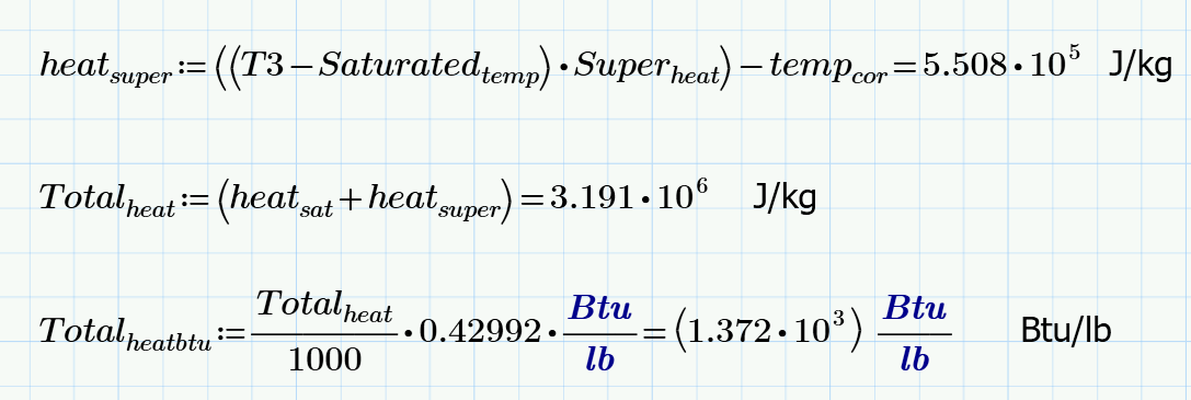 Figure 16: Formula that calculates the heat content of steam within the steam chest So the formula calculates the heat content of steam at 850F and 2000psi as 2.64x10⁶ + 5.508x10⁵ which equals 3.191x10⁶ J/kg or 1372 Btu/lb, this compares to 1371.84Btu/lb from the SpiraxSarco web site, an error of 0.16Btu/lb or 0.01%. The error increases to a maximum of around 1.5%, at 750F and 800psi. Provided temperature is maintained at above 800F the error across the conceivable pressure range in the steam chest is <1%, the error is largely associated with the Superheat term hence the correction factor. The PLC using the above formulas calculates the specific heat content of the superheated steam several times a second. The previously calculated steam density and swept volume is used to calculate the amount of steam being removed. 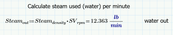 Then the heat removed from the generator is simply the mass flow rate x the heat content. 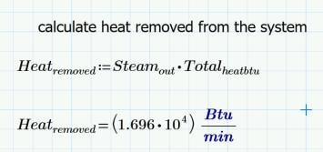 The generator efficiency is estimated from the relationship between mass flow rate/ heating surface area, the generator has been sized to achieve ~80% efficiency at full power. Since we now have a value for heat removed in BTU/hr the fuel demand is simply calculated from: 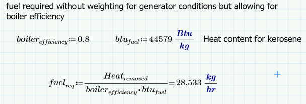 approximations within this approach, will be such that equilibrium is unlikely to be exactly achieved, as such temperature and pressure will rise or fall during operation in proportion to the errors within the calculations. There are various permutations. However, in simplistic terms (for the sake of this article) there are four basic scenarios, temperature to low or too high, and pressure too low or too high. 1. If temperature is low but pressure is good, then there is excess water in the generator, i.e. the water to saturated steam transition is too high up the coils. The remedy is to reduce feed water input. 2. If temperature is too high but pressure is good, then there is excessive heat and insufficient water. The remedy is to reduce burner input, and increase feed water (a normaliser can be used to control excess temperature. However, additional feed water must also be added at the bottom end to remedy the situation.) 3. If pressure is low but temperature is good, then again there is insufficient water in the coils. The remedy is to increase feed water and heat together. 4. If pressure is high but temperature is good, then there is too much water in the coils. However, both water and fuel must be reduced together. Formula for temperature and pressure correction factors have been created. These are used to bias the fuel demand and water delivery. Therefore, the initial fuel and water demand, which was calculated from heat/ steam being removed, is either increased or reduced according to the conditions in the steam generator relative to the operating set point. Clearly if either the boiler efficiency or the steam usage is significantly out, then the system will find equilibrium away from the desired set point. Therefore, trim pots are provided on the control interface to allow the boiler efficiency and or the leakage factor to be adjusted to bring the convergence in line with the operating point. An error in efficiency would result in issues related to heat input, errors in steam usage would result in issues with feed water rate. If steam usage was underestimated, then we will see an increase in temperature with a falling pressure. This is because there is a reducing water level in the generator. Therefore, the leakage factor must be increased. Should pressure be high and temperature low, then steam usage is overestimated and leakage factor should be reduced. Note the reduction in calculated steam removal has the effect of reducing both feed water and heat input proportionately. Therefore, pressure should reduce. However, temperature will be maintained via the reduced water level within the coils despite the proportional reduction in heat input. Should boiler efficiency be underestimated then we will see over temperature and over pressure. In this case boiler efficiency factor should be increased, this will reduce the fuel delivery. Should temperature and pressure be low, then boiler efficiency has been over estimated and the boiler efficiency factor should be reduced, thus increasing fuel delivery. So leakage factor increases or decreases feed water and fuel in proportion Boiler efficiency either increases or decreases burner input alone. There are three control modes:
Minimum Burn: At its lowest fuel pressure setting and with the return line fully open, the burner delivers approx. 1.2gal/hr. In this setting the burner cuts in and out at the operational point for pressure and or temperature, the fan continues to run at low speed to prevent a damaging heat soak, which could otherwise occur. The system stays in minimum burn, whilst demand is less than the minimum burn value (1.2gal/hr). Speeds in excess of 30mph will be required before demand exceeds minimum burn. PRV control: Once demand for fuel exceeds minimum burn mode, the system automatically switches to PRV control. Now the system varies the PRV position in the nozzle return line to match fuel delivery to demand. As the demand increases, the PRV progressively closes. The return flow meter is used to calculate fuel delivery. However, as the PRV approaches fully closed, the low flow starts to make the flow meter readings unreliable. As such, an algorithm is used to calculate return flow from PRV position at the final stages of closure. Unlike in minimum burn mode, the system modulates around the desired operating point. As previously described the fuel demand and water is modified based on generator conditions. Therefore, if pressure exceeds the operating point, this results in a reduction in fuel and feed water. The reduction progressively increases the further from the operating point the system gets. If this results in reducing steam temperature, then the feed water will be cut back further still. If the steam temperature actually rises due to the reduced feed water, then feed water is increased. Should the control system fail to keep the pressure and or temperature within the upper operating band around the set point, the system will drop into minimum burn mode. Once conditions return to within the operating band, the burner will ramp back up to the required demand again. Should, however, even minimum burn mode not prevent further pressure and or temperature rise, then upon reaching the safety limit the burner and feed water will fully shut down. Speed Control mode: Once fuel demand exceeds PRV mode, the return line valve and PRV are fully shut. Now fuel delivery is varied by increasing fuel pump speed. This has the effect of increasing fuel pressure in the fuel rail. Fuel pressure can be varied from 100 – 300 psi and at 300psi this gives 9.9g/hr. Modulation (including shut down) is as described for PRV control mode. Feed Water control The water pump is driven from the output shaft of the engine via the free-wheeling hub Therefore, even when coasting, the water pump is driven via the back wheel. However, no feed water is available when stationary. The outlet from the feed water pump has a recirculation line back to the inlet port of the pump via a solenoid valve. When this valve is open, no water is delivered to the generator. It is a simple task for the PLC to modulate the solenoid valve to control the proportion of water delivered. In addition, an offtake from the pump delivery goes to a second solenoid valve and from thence to the normaliser. Should the stem outlet temperature be too high, then the normaliser solenoid valve opens and allows cold water to injected to the top coils of the generator. The feed water entering at the bottom has an increased pressure compared to the steam leaving the generator at the top, due to the pressure drop related to velocity within the generator. As such the pressure delta increases with demand and so the fixed orifice in the normaliser nozzle has been sized to deliver approximately 10% of the feed water rate for any given speed and demand. The normalizer nozzle should consist of an orifice followed by approximately 3 inches of shroud within the steam main. This shroud is heated by the superheated steam. The water spray entering the shroud (via the orifice) is heated and turned to wet steam within the shroud before it mixes with the main steam flow, ensuring good mixing and efficient heat transfer between the gaseous fluids. If water is merely injected straight into the super heater coil, then the water droplets bead like water dropped on a hot plate and the effectiveness of the system is much reduced, (remember at full demand the velocity in the superheater is >75ft/sec), with a mix of wet and superheated steam leaving the generator outlet. The water pump is fixed displacement, thus the feed water rate is calculated from engine rpm and validated by a flow meter within the suction line to the pump. A non-return valve on the pump inlet ensures that when in bypass mode, the internal pressure in the pump is largely maintained and not just lost back to the water tank. An electric boost pump ensures that pump inlet conditions are maintained to prevent cavitation. Part two will follow after further updates to design and testing.
0 Comments
Leave a Reply. |
Archives
December 2022
Categories
All
|
 RSS Feed