|
Steam Car Network
|
|
Billy Barnes Land Speed Record by Rick Heinig credit to the Steam Automobile Club of America PART ONE One of the main reasons for visiting Billy was to discuss how he ran the mile at Loring Airport and or the Ohio Mile along with what key elements lead to his success to date. The general agenda to the visit was to talk about the record attempt, the configuration, and how the “D” slide valve was set up. I was traveling to Georgia to talk with another steam Land Speed Record (LSR) seeker, Bob Sarda (another future article). I met with Billy Friday afternoon October 29th, 2021 at his shop. One common element between Billy and me is that we both have a 10 HP Stanley Engine. Actually, Billy has several engines and is in the Steam car restoration business following in his Dad’s footsteps. I’m in the process of rebuilding my 10 HP Stanley engine and was curious to any insight that Billy could offer me. I do want my Stanley car to be a real good performer. I present this article here for I think it would be of interest to SACA readers. Hope you all enjoy it. Billy’s shop is old school. Nothing like using vintage equipment to build and repair period steam automobiles. I got the nickel tour. Barnes’ shop is at 1728 Glenwood Avenue, Lewistown, PA. It is about a three hour drive south from where I live in the Elmira/Corning, NY area. There are all kinds of Stanley steam engines and cars around his shop. One was a neat looking Steam travel all type of car or should I say coach bus. I saw progress on a Stanley K, Gentleman’s Speedy Roadster (GSR), which will sure to be a stellar speedy performer. The K will receive the same size Stanley engine that goes into the Mountain Wagon. The steam engine is a twin cylinder, double acting 4-1/2 X 6-1/2 bore and stroke respectfully. This same size is what Billy says ran the LSR for the Stanley brothers in the early 1900’s. I can surmise that Billy is all about speed. From then on we started talking about land speed records. Billy holds the land speed record for a steam powered motorcycle as shown in the Loring Timing Association Certificate - picture(s) at slightly north of 80 mph over 1-1/2 miles. Also included is the East Coast Timing Association Certificate as pictured. Billy described one of his steam motorcycle speed record attempt. He starts off with relatively low pressure (200 – 400 PSI) in fear for someone getting hurt in case of a boiler rupture while building pressure before the race. He likes to run the mile at 1,000 PSI and with the engine set at cut-off, AKA hook-up and full burner all the time. He literally just gets rolling and goes into hook-up. At the start of one of his runs, he was just slowly moving along because his boiler pressure wasn’t up to where he wanted it. The race monitor called out to Billy asking if everything was alright. He was following in a chase truck. It is hard to explain the situation with steam and building up pressure. As the bike speeds up, the draw increases on the burner through the fire tubes and greatly increases the boiler pressure. He has his engine steam exhaust set up to help draw the combustion gas through the fire-tubes. It is a non-condensing system. Billy runs a custom motorcycle frame; 10 HP fire-tube type, Stanley boiler, and 10 HP Stanley engine with hook-up. The engine would be considered a dry engine (oiled before each run). His bike is pretty much a standard motorcycle frame with standard wheels and brakes. Not too many frills and enough equipment to get the job done. Gear train is from engine to a jack shaft and then to the rear wheel. The gearing is set for an engine speed of ~500 RPM to produce 100 mph. No need for feed water pumps nor check valves and just the bare essentials to run a mile at speed. He just runs with the energy stored in the 10 HP Stanley fire-tube boiler. 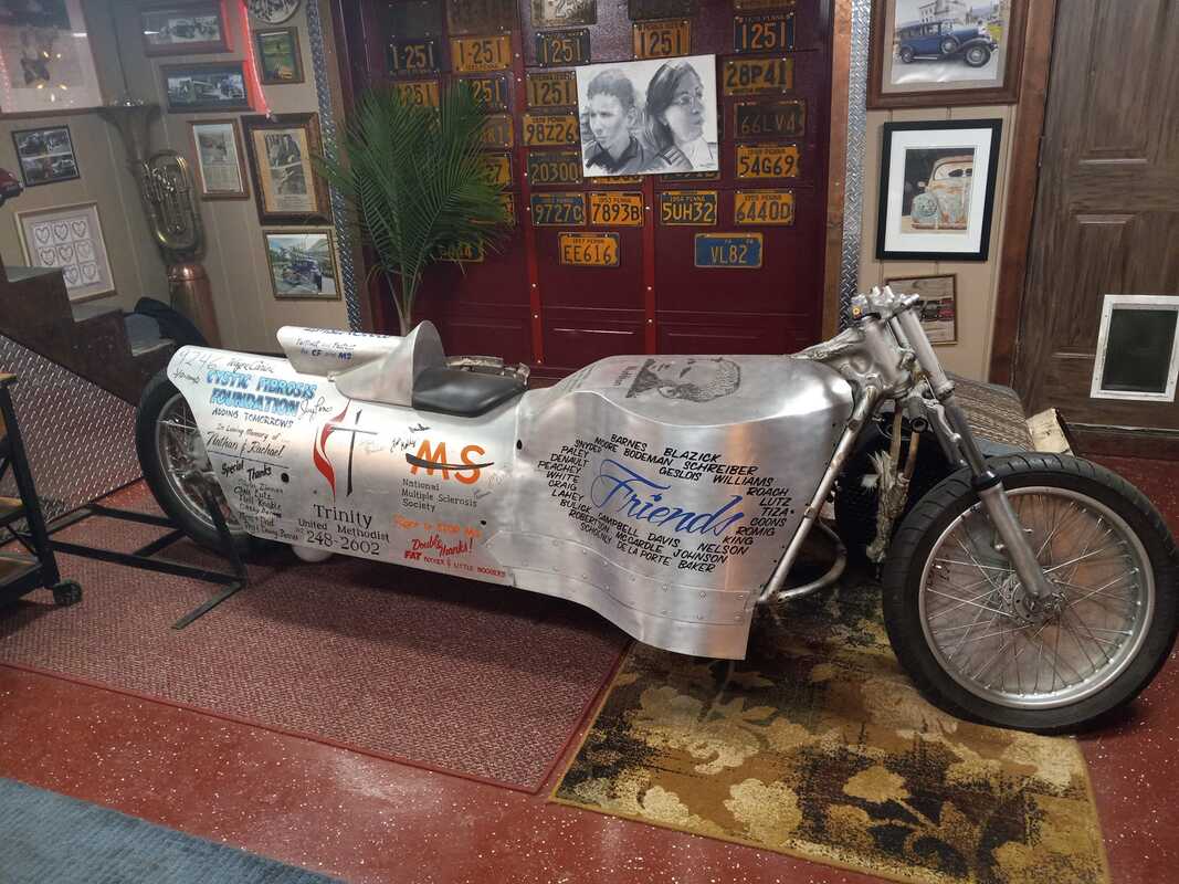 From a personal interest of mine, I wanted to know more about the steam engine valves and was a large part of my reasoning to visit Billy. I own the same 10 HP Stanley engine that I’m using on my 84% scale version of a GSR. My engine is an earlier version where Billy’s is a later version with hook-up. Note that a 10 HP Stanley is a 3 X 4 bore and stroke respectfully. One of my keen questions on running the mile is how you set up the valves. We discussed at length the steam lap, exhaust lap and lead on the engine. Billy refers to the lead as timing. One secret to the valve setting is to set the timing in the hook-up mode. At piston top dead center, the valve needs to be slightly open allowing steam into the cylinder. It is like the early days with cars where advancing the spark. This allows steam to enter the cylinder before the piston reaches top-dead-center. Why? After some deep thought on the matter, the reason is that when running steam engines at speed in hook-up, they have something known as wire-draw from the valve. The speed in which the steam travels (mass flow rate) isn’t quick enough to fill the cylinder and get enough power through the shortened admission in cut-off. Also, the key reason for running in hook-up is to conserve the steam at pressure and allow for it to do its expansive work in the cylinder. Pressure correlates to engine speed and that’s what is needed to set speed records. Hence the reason he runs with the 1,000 PSI pressure.
After my Barnes’ visit, I spent some time looking at my 10 HP engine and doing a valve simulation. Then imagined what happens to the valve travel in hook-up. I believe that the way the eccentrics are positioned in the Stephenson’s Linkage that, when the valve mechanism is lowered, the resultant valve travel allows for the increase in lead. This confirms Billy’s statement to set the timing the way he does. He even says the engine runs smoother. Very interesting information and gets me thinking about setting up my own engine on my GSR. So I set up a valve simulation with the crank angle, eccentric angle setting, and valve lap (mainly steam lap). Each eccentric is positioned 135 Degrees from the crank position, one for forward and the other for reverse. From the pictures, the crank is measured to the keyway, and eccentric to the keyway to establish the 135 degrees. This information establishes the initial set up for a valve simulation. One of my questions to Billy was “What if we increased exhaust lap to conserve pressure”. He is willing to make a valve like this to check it out. I want to do more simulation before we go to metal. Another question I ask myself pertaining to steam engine design, do you set the angle, the Lead, and then apply Lap. I believe the angle of the eccentric sets the cutoff at least as the starting point. Also there might be a reason for this angle setting in concert with the reverse eccentric to help with the advance that Billy would set with hook-up engaged. In looking at the picture of the end view of my eccentric, at top dead center, both the valve rod followers will favor the one side at top-dead-center. So, when pulling into hook up, the valve timing (as Billy describes it) will be advanced. I wonder if all Stanley Engines are configured this way. If this were the case, then all Stanley’s will start with 50% cut-off. My research is not complete as of yet. I’ll be observing and evaluating as I rebuild my engine for my GSR. Back to Billy and his plans, he will be trying to improve upon his record with a new built engine with aluminum pistons and valve settings as described. He has a recommendation to a would-be LSR car builder to use two (2) 20 HP Stanley Engines on top of one another with the crank gears in mesh. I believe that this is actually a good idea. We’ll be keeping a look out for Billy’s next LSR attempt. And we’ll keep egging him on to run the next motorcycle, steam LSR and perhaps LSR automobile. Last thing to mention about Billy Barnes is that he is passionate about Cystic Fibrosis (CF) and Multiple Sclerosis (MS) for personal reasons. Jay Leno indorses Billy; he would ask you to give to this worthy cause(s). Thanks for reading and look for a future SACA presentation about valve timing on my 10 HP Engine. Kind regards, Rick
0 Comments
Billy Barnes Land Speed Record by Rick Heinig credit to the Steam Automobile Club of America PART TWO 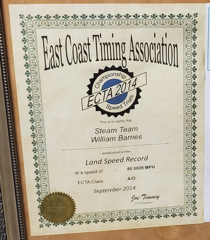 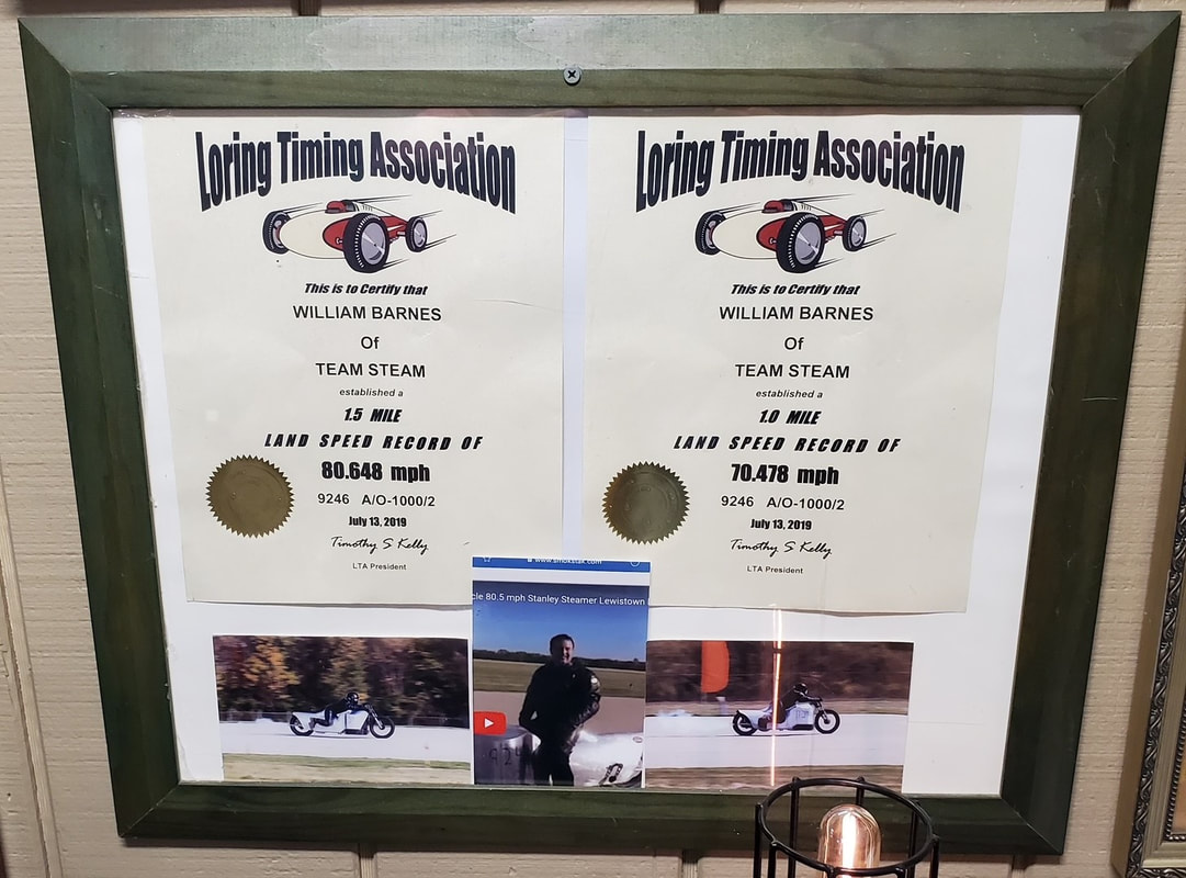 The East Coast Timing Association and Loring Timing Association certificates awarded to William (Billy) Barnes known as the Steam Team. Billy holds the land speed record for a steam piston powered motorcycle. 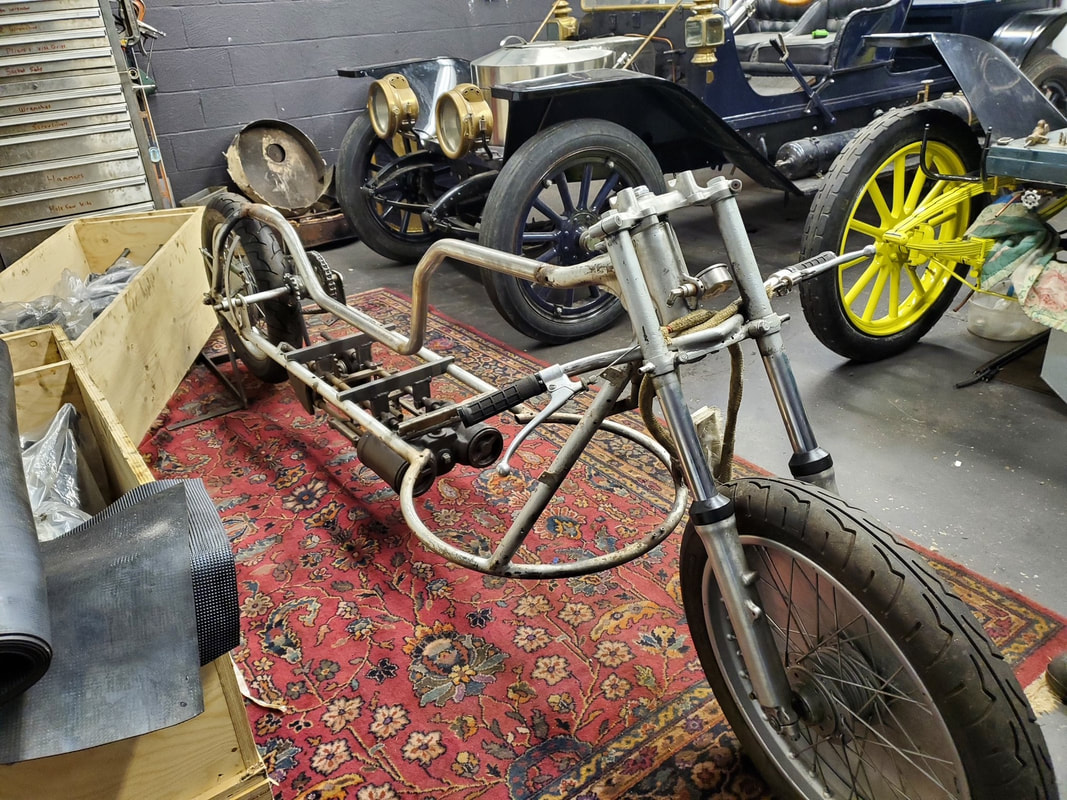 The motorcycle frame that was used to set the land speed record for a steam powered motorcycle. The round portion is where the Stanley 10 HP boiler sits. 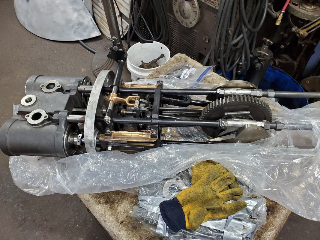 This is a brand new, customer's 20 HP Stanley Engine just uncrated. It was shipped in from the UK. It is slated to go into a Gentleman's Speedy Roadster 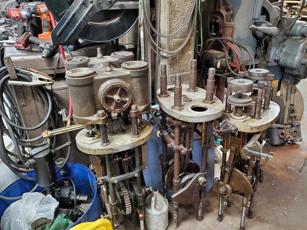 Billy is no stranger to Stanley Engines. His shop is full with new, used and pieces of Stanley Engines for incorporation into customer's cars, rebuild or components for rebuild.
Billy Barnes Land Speed Record by Rick Heinig credit to the Steam Automobile Club of America PART THREE BELOW 10 HP Valve Simulation Initial - The first view of the D-slide valve establishes the valve and its steam and exhaust lap. It is centered over the port openings. The second view is to establish the 135 Degree angle from the eccentric picture exercise. This establishes the lead on the engine. 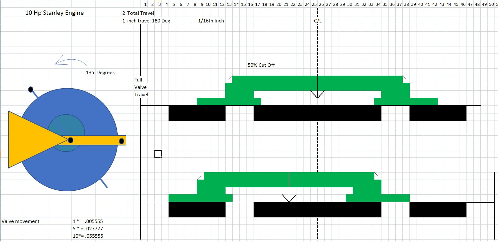 BELOW 10 HP Valve Simulation - This shows the valve movement starting with the piston at top-dead -center. The establishment of the eccentric angle (lead) and lap shows the 50% cut off. I believe that the design intent is to establish the lead angle first and then determine lap to get the proper cut-off. 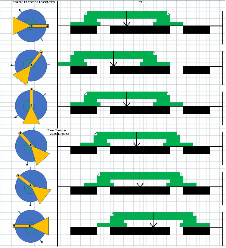 BELOW Crank Throw Angle - using a picture and paintbrush, this identifies the crank throw angle relative to the key way. 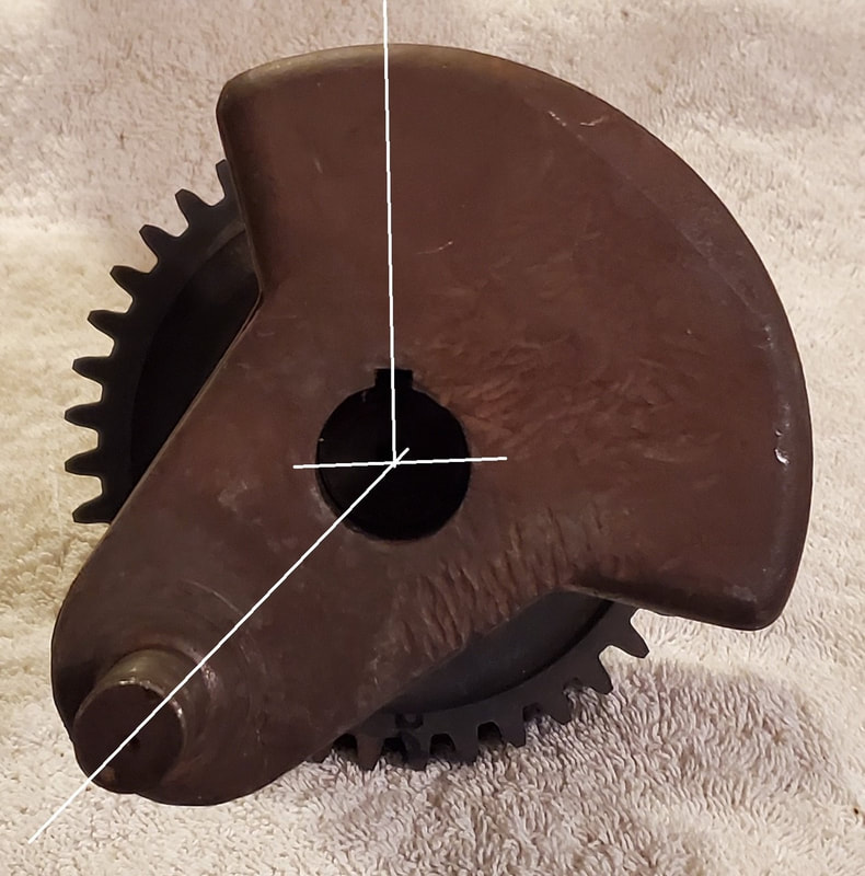 BELOW Eccentric Angle - picture shows the eccentric angle relative to the key way. The relationship between the key way establishes the 135 Degree angle between the crank and eccentric. This happens to be a key feature to establish the 50% cut off in the 10 HP Stanley Steam Engine. 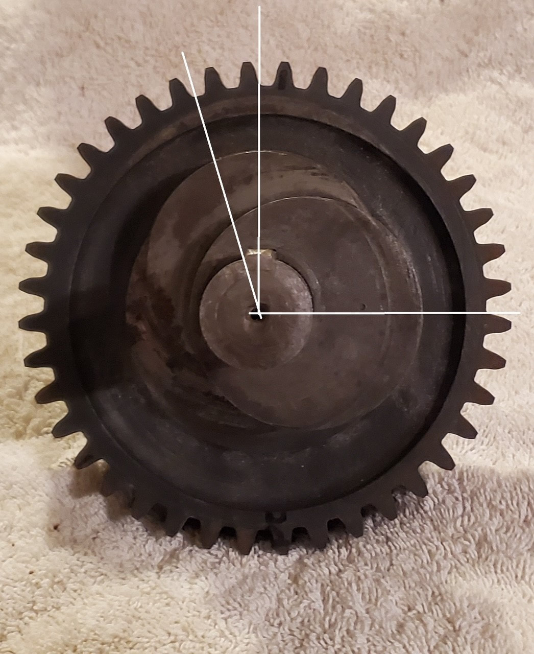 Billy Barnes Land Speed Record by Rick Heinig credit to the Steam Automobile Club of America PART FOUR About the Barnes Burner, it is reported that it does not howl and will not blow back. The construction is made out of stainless steel with welded seams to not allow any puddling of gasoline that will auto ignite when not wanted. Billy does rebuild and build Stanley fire tube boilers, new for customers. One of his latest boilers was for Herb de la Porte and his Locomobile. 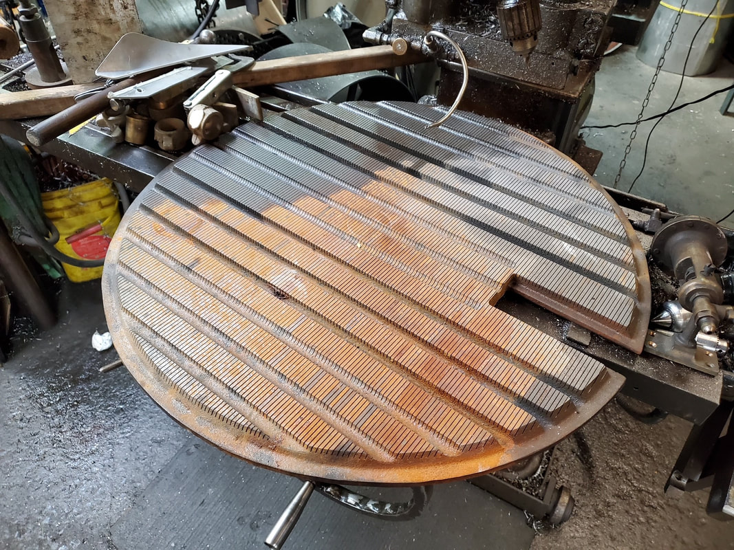 Please give to Cystic Fibrosis and Multiple Sclerosis (within the picture already) 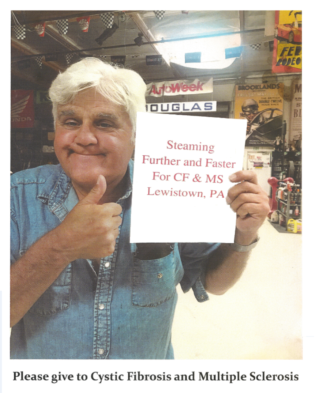 burner on the Model 85 stanley11/27/2022 JOE SHUKAY Front of the burner on the Model 85, showing branch forks, end of vaporizer pipe, clean out cable, pilot, igniter and branch fork nut and compression washers. An Electronic Boiler Water Level Gauge. By David David K. Nergaard
Part One Every operator of a steam car with a boiler having a distinct water level needs to know what that level is at all times. This is important in a Stanley boiler but is critical with many other boilers such as the Baker and Derr. Many cars were fitted with thermostatic water level sensors, of which the Stanley three tube indicator was, perhaps, the most common. These were often reliable in use, but gave no indication what ever when the boiler was cold. Hence, some independent means of verifying the water level before lighting the fire is needed. It is also desirable to have a sensor with a remote indicator. Thus, the sensor can be mounted to give a correct indication of water level regardless of the slope of the hill being climbed while the indicator is still easily seen from the driver's seat. Some years ago, I considered various types of electronic level sensors, many of which I had used as tide or wave height sensors in my years as an electronics engineer in oceanography. Most of these required rather sophisticated electronics mounted directly at the top of the sensor. To work as a boiler water lever sensor, they would have needed more than a order of magnitude increase in sensitivity and the ability to work at the temperature of the steam in the boiler, nearly 500 degrees in the case of a Stanley. I came to the conclusion that something different was needed. Eventually I conceived a type of water level sensor which should be equally accurate whether cold or under steam and which could use a remotely sited electronics circuit. The sensor is a coaxial capacitor in which the central conductor is an insulated rod of comparatively small diameter. The outer, and grounded, conductor is the outer housing of the gauge when empty and the surface of the water touching the insulated rod surface when full. The formula for the capacity per unit length of a coaxial capacitor is a constant times the dielectric constant of the insulating material divided by the logarithm to the base ten of the ratio of the outer radius to the inner radius of the conductors. For measurements in inches, the constant is 0.614 picofarads per inch. I assumed the dielectric constants of air and steam differ only slightly from that of a vacuum. If so, the capacity of the empty gauge should be about that of a bare centre rod in the pipe chosen as the gauge housing. For a one quarter inch diameter rod in a piece of nominal one inch pipe, this calculates to about one picofarad per inch. For the wet part of the sensor, the inner radius is that of the rod, the outer radius is that of the rod plus the thickness of the insulating layer and the dielectric constant is that of the insulation used. Assuming a thickness of 0.01 inch and a dielectric constant of 3 yields about 40 picofarads per inch. This is large enough to be easily measured. The measuring circuit can be connected to the gauge with a length of coaxial cable, which merely adds some capacity to that of the empty gauge. I put together a ten inch long test unit using heat shrink tubing on a bit of one quarter inch copper tube for the centre rod mounted in a piece of one inch iron pipe. The measured capacities of this device were; cable, 73 pF., empty gauge, 20 pF., and full gauge, 317 pF. It was not what I had calculated, but quite good enough to make a workable gauge. There is a common and inexpensive integrated circuit used as a timer. It charges a capacitor through a resistor connected to its supply voltage and generates a pulse whose length is R x C seconds long each time it is triggered. The CMOS version of this device is the TMC555, costs about a Dollar and uses very little power. Even more significant, this version can run faster than the less efficient bipolar transistor versions. In particular, it works beautifully with a resistance of 100,000 Ohms and the sensor described above. The 555 timers can be wired to trigger them selves; thus making an oscillator whose frequency is inversely proportional to the resistance and capacitance used. I breadboarded a circuit using three TMC555s, a low power operational amplifier and an efficient low power voltage regulator. The first timer generated a pulse of length determined by the capacity of the sensor. The second was adjusted to make a pulse equal in length to that made by the first one when the sensor was empty. The third ran as an oscillator and triggered the others simultaneously. All three were powered by the voltage regulator. If one averages the voltage of a series of pulses, one gets gets the voltage of the pulse times the period of the pulse divided by the period between pulses. An operational amplifier (op amp, for short) can be connected to subtract one voltage from another while doing the averaging. Thus, it can subtract the output of the second timer from that of the first and drive a meter with a current that is zero when the gauge is empty and full scale when the gauge is full. Adjusting the period of the second timer sets the zero and adjusting the third timer, which sets the number of pulses per second, adjusts the full scale reading. As the timers use regulated power, the voltage of the battery powering the circuit does not affect the accuracy. For an indicator, I used a Weston type 301 10 milliampere meter of about the same age as my car. Thus, it doesn't look too out of place on the dash and is already conveniently calibrated to read 0 to 10 inches! The meter draws more current than all the rest of the circuit. This is not an issue in a condensing Stanley as the circuit can be run by the existing electric system in the car. How did it work? Beautifully the first time, the meter rising smoothly as I filled the gauge. However, as I emptied the gauge, the meter dropped only slightly and very slowly. A thin film of water on the rod is just as good an outer conductor as a half inch thickness is. And water easily clings to ordinary heat shrink tubing. Experiment result number one: the insulation on the centre rod must not be wetted by the fluid being measured! The immediate logical answer to the problem was Teflon. And, it is available as heat shrink tubing. However, it is not cheap and is normally sold in batches of 100 pieces. After some conversations with the electronic supply house I use, the manufacturer of the tubing very kindly sent sample lengths, a yard each of three different sizes, free of charge. The rod was recovered with a piece of this and the resulting system was demonstrated at the December 2004 meeting of the North-east chapter of SACA. On that occasion, it worked very well, running on a 6 Volt battery. By the way, the dielectric constant of Teflon is about 2.7. There were still questions about whether it would work under steam. The following spring, it was tried on my Stanley, being mounted at the left side of the boiler just forward of the throttle. And the answer was yes, but... My contact to the centre rod was through a modified sparkplug at the bottom of the gauge. It soon developed electrical leakage which essentially shorted the gauge. It was not a dead short, but enough to render the gauge useless. I moved the connector to the top end where any similar problem would not be wet, and that cured that one. However, apparently a thin film of water can form on the sparkplug insulator when it cools down so the gauge often reads pinned full with a cold boiler. It does not do this if the boiler is empty, only if it is left with water in it over night. Sometimes, rapping the gauge at the top shakes off enough of the water to make it read correctly, but not always. I think a new connector fitting using a Teflon insulator will cure this issue. A second problem was more subtle. For the first few hours the car was steamed, the gauge gradually read higher although the water level shown by the original bronze bottle gauge did not change. The readings did stabilize, but after the car was steamed about a half dozen times, it failed completely; shorted out. A post mortem examination gave a possible explanation. When the Teflon tube was shrunk onto the centre rod, a small air gap was trapped inside the tube. The resulting increase in "insulation" thickness explains the lower than expected "full" capacity. Under steam, the air in the gap was gradually replaced with water condensed from the steam, which effectively reduced the insulation thickness, making the gauge read almost 30 percent higher. Okay, recalibrate and go on. Then came the kicker; when the boiler was blown down, that water tried to flash into steam, stretching and, finally, splitting the Teflon tubing. Back to the drawing board, again. My next attempt was to get a new piece of tubing, stainless steel this time, Teflon coated by a commercial firm specializing in such work. They did it free as a manufacturing sample. Fitted to the gauge and tested cold, it looked very good; very good leakage resistance and much higher capacity per flooded inch. But, as soon as there was steam on the boiler, the leakage resistance worsened sharply. The gauge was useless long before there was any measurable steam pressure. Pulled out after only a few hours steaming, that part of the rod which was under water has a curious crazed and bubbly appearance. The part exposed to steam does not have this appearance. Repeat last sentence of previous paragraph. Small Parts, Inc. now sells Teflon heat shrink tubing in single lengths, which makes it reasonable to continue experiments. I made a new centre rod using thin wall brass tube with small holes drilled through it every half inch. The theory was they would allow trapped air to escape during shrinking of the Teflon, reducing the resulting air gap. Also, any possible "flash" steam behind the Teflon tubing could easily escape. So far as it goes, that worked. That sensor was in the car all last season and worked quite well. It is remarkable how quickly the gauge responds. Swiftly going through a few ess curves will make the indicated level swing through a range of about six inches! Mounted where it is, it shows the correct level on any hill and is not affected by acceleration or braking. It still has the cold insulator problem noted above. Towards the end of the season, it developed a problem. If the water level got more than two inches higher than normal, or about eight on the meter scale, the gauge would abruptly read full, pinned. When the water level dropped again, it behaved normally. I suspected a flaw in the Teflon about two inches from the top end, and that is what I found when I pulled it apart at the end of this year's driving. Above the break, the Teflon looks perfect. Below the water level, there was some black dirt, probably iron oxide, but it had no effect on the gauge's operation. At the normal water line, it is a little dirty but showed no other sign of wear. At this time, I have only a guess as to why it failed. Teflon heat shrink requires a rather high temperature to make it shrink and the only way I could do it was over a gas stove burner. I may have gotten that part of the "rod" too hot. At this point, the gauge has worked well enough that others should be able to build working units. Maybe they can improve on my attempts. I will rebuild it this winter, with a new all Teflon connector insulator. The electronic circuit I have used draws only a few milliamperes, plus the current through the meter, 6 milliamperes at "normal" water level. Thus, an ordinary 9 Volt transistor radio battery, NEDA-1604, should run the gauge for about 50 hours. If a one milliampere meter movement is used, even longer battery life will result. This means that the gauge can be fitted easily to any steam car, with a small internal battery if needed. It can be made to any convenient length. Thus, it can still be on scale when the low water automatic has shut off the fire. Most important, it gives valid readings when any of the water level devices ever fitted by Stanley are "off scale", and can do so even when the boiler is cold. The circuit I used is hand wired on a prototyping board less than 3 inches by 4 inches. It fits in a 2 X 3 X 5 inch aluminium box with plenty of room for a suitable battery. I am investigating the cost of having a printed circuit board made. I strongly suggest using a Teflon insulated coaxial cable, such as RG179B/U, as the sensor cable, considering the temperatures to which it will be exposed. Unfortunately, it is usually sold in lengths of 100 feet or longer. I used a bit from my junk box. It has held up well for the four seasons it has been used. new design Stanley syeam car burner jets3/30/2022 Joseph Fedullo Thanks for your interest in these multiport jets. It has been a learning experience having them made and it took longer than I hoped. I have not had an opportunity to try them out yet. Hopefully they work well. This was the first, and after dealing with the suppliers, the last run I plan on making. I used an online prototyping company called HUBS.com to manufacture them. It took 2 iterations to get a decent part. They cost me $12.50 per jet assembly in a quantity of 200. If you need more, I can share the CAD files and you can get them sourced. Preparation: These jets will require a little effort on your part to perform their best. First, the main orifice hole at the tip will need to be upsized. It was intentionally undersized to allow the user to modify it to their needs. As delivered, it is drilled at 0.032” (which is about a #68 drill) This will need to be opened up to the size of your choice. I advise trying one size smaller than you would normally use as a starting point. Since these jets do not have the restriction of the long length orifice hole of the commercially available multiport jets, they may flow more fuel for a given orifice size. Start small, and if it isn’t flowing enough fuel, it is an easy matter to go up another size. Please disassemble the two halves when you are upsizing the main hole to prevent chips getting stuck in-between the halves. I finger tighten them together, but you may need a 5/32”wrench to separate them. 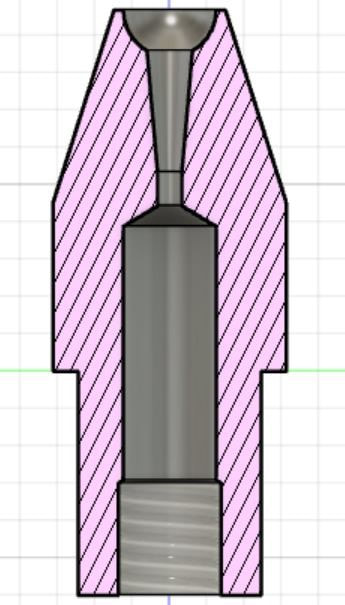 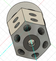 To prevent a carbon fleck from getting to the main orifice the feed holes on the inlet must be smaller than the main orifice. I would say at least 3 drill sizes smaller than your main orifice to act as a filter. There are so many feed holes there is probably no need to enlarge them at all from the existing #68s. I haven’t had an opportunity to test both ways to see if there is an advantage to opening them up, but I suspect there is not. I have a few spares I will experiment with and follow up. It should take quite a while for carbon to build up on enough of these feed holes to restrict flow. But when it does come time to clean them, do not just push the carbon in the same direction as the fuel. If you do, it may clog the main orifice. I recommend blowing them out with compressed air fed through the outlet tip counter to the way fuel would flow. If you prick the holes clean - unscrew the two halves and blow them out after to make sure you did not leave carbon in between the two halves. If you ordered the jets with a 5/16” head (same size as original Stanley) they were designed to maximize air entrainment around them. If you use the standard copper washer to seal it to the branch fork, the OD of the washer will stick out a little diametrically and potentially disrupt air flow. McMaster Carr part number 97725A100 is a more appropriately sized copper washer for the 5/16” head. The OD of these is almost identical to that of the branch forks on my cars so I do not think they will pose any aerodynamic obstruction. They are $13.03 per pack of 25. You can also try no copper washer (How Stanley did it originally) or just use the larger washer as the disruption in air flow is likely minimal. A note on tightening – some of the sections are kind of thin. Hand tight is all you need between the two halves of the jet. Tighten to the branch fork as normal - just enough to seal. Don’t go crazy. Support the museum: The jets cost me $12.50 each, and that is what I am charging you. I did this for the hobby, not a business. The other commercially available multiport jets cost $25 each ($50/pair) and aren’t nearly as difficult to make. If you like these and feel they were worth more than you paid, I ask you to consider making a donation to the Stanley Museum at: 40 School Street, P.O. Box 77 Kingfield, Maine 04947 Phone-(207)-265-2729 [email protected] Tolerance issue: The first batch of parts was out of tolerance in several locations, so I had them remade. The second batch (what I am shipping out) were much better, but the central hole on the inlet was drilled too deep. It shouldn’t impact performance, but am working with the supplier to see if they will remake again. I did not want to further delay shipping so I am shipping these as is. The end of the inlet section is thinner than I designed. Please be careful when pricking. If you break one, please let me know and I can sort through the first batch that was out of spec to find a replacement. 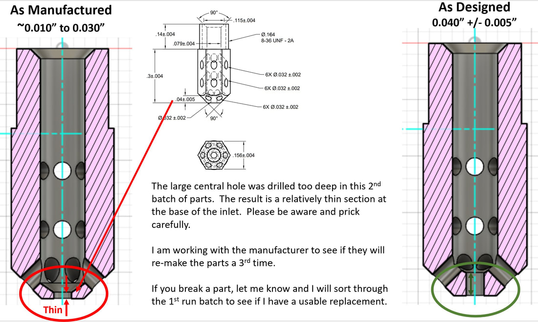 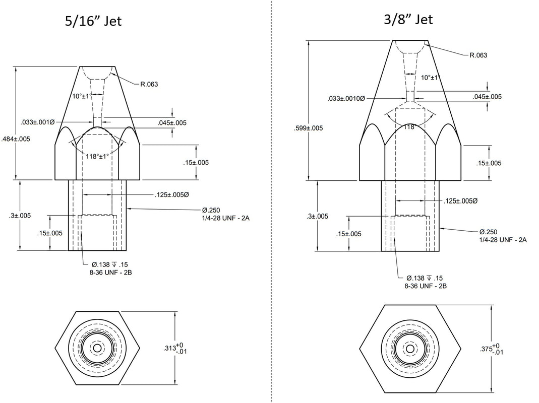 LEON-SERPOLLET WINS BEXHILL SPEED TRIALS 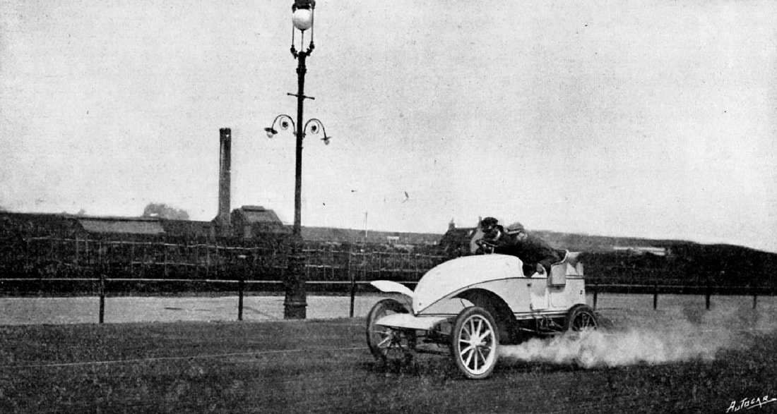 1902. Leon Serpollet taking a trial spin at Bexhill. When Mr. J. H. G. Hamilton, to whom we are indebted for the photograph, "snapped" the car, it was going at about fifty-two miles per hour. Autocar 07.06.1902, P.600 1902 If you look closely at the 19.05.1902 Trial Bexhill publications, it is apparent that Leon Serpollet used two different cars. Why did it happen? Having studied the reports of the day I can now share my findings. 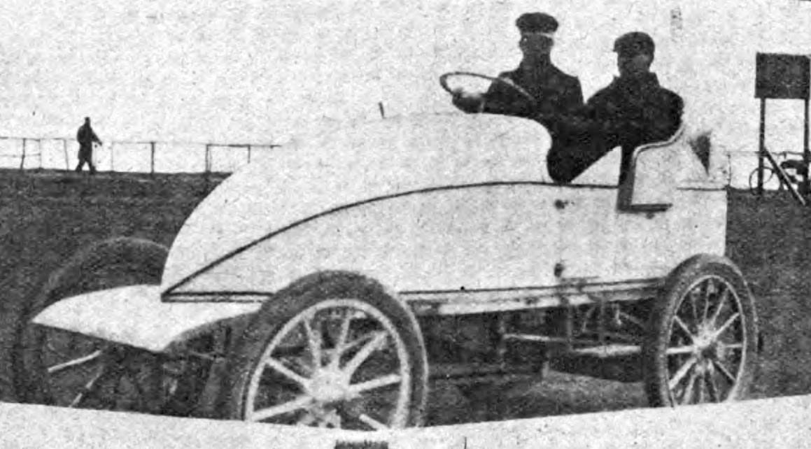 1902. New racing car Gardner-Serpollet 120 bhp. This car was longer than the Nice race car. External differences are also another front fairing near the springs, triangles on the doors, a wider seat. This car was not an Easter Egg. The Motor-Car Journal 31.05.1902 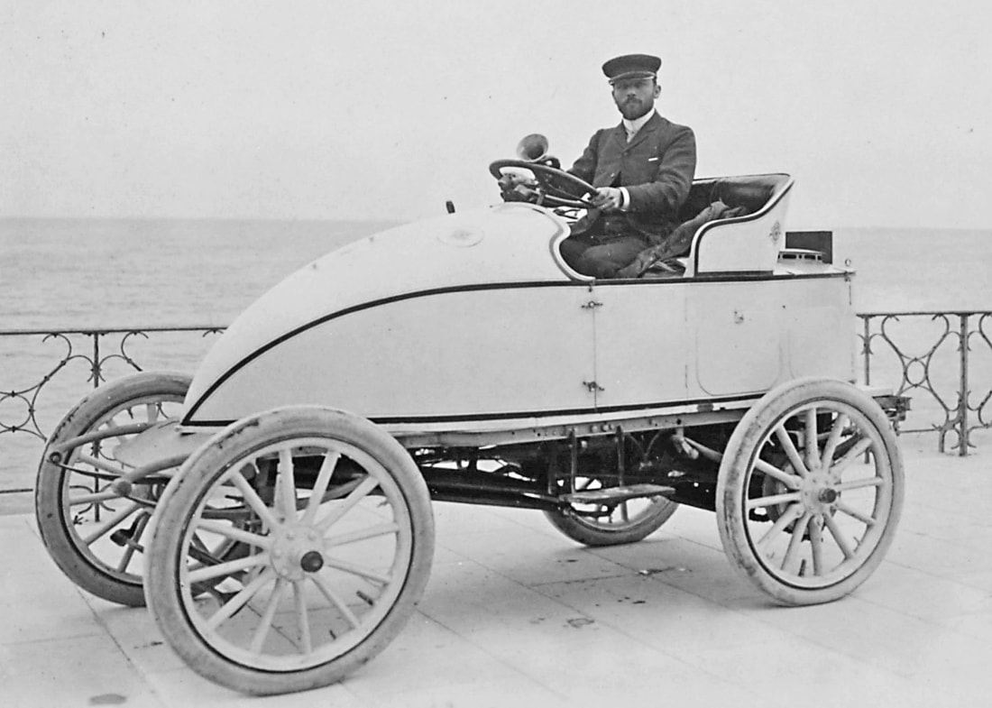 1902. Racing car Gardner-Serpollet 12 hp (45 bhp) from Nice. This car was an Easter Egg. Photo Jules Beau 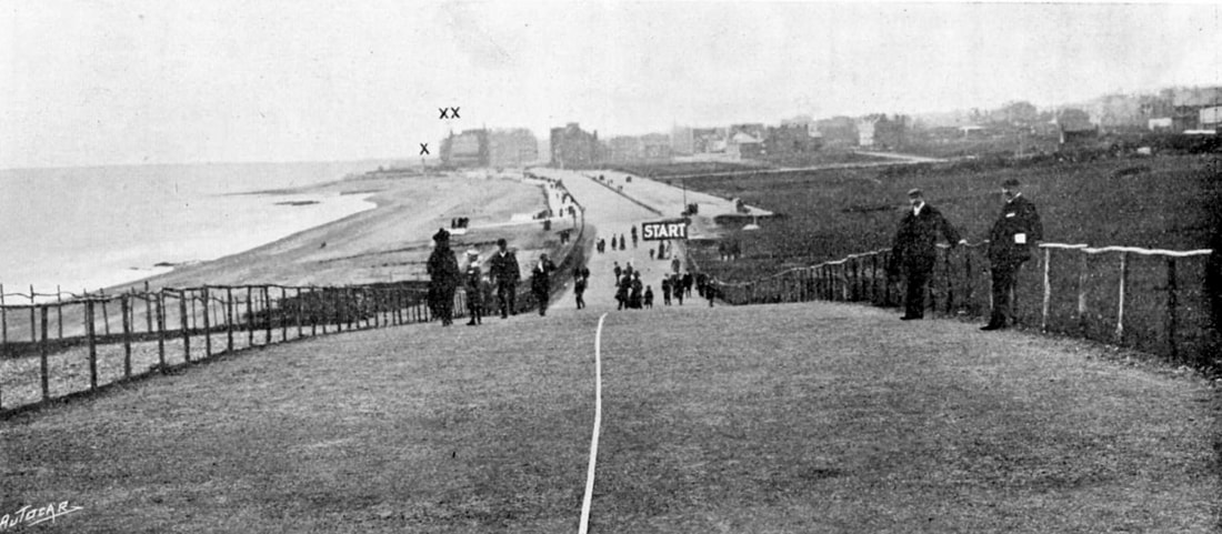 A view of the track from the summit of Galley Hill. This hill is 155 yards long. The cars started from the top and were timed from a point at the bottom where a board was exhibited bearing the word " Start. ' The point marked X is the Chalet, on the top of which was a telegraph board on which the numbers of the various winners were exhibited, and X X indicates the position of the Hotel Sackville. A broad tape was nailed down the center of the course at intervals. The first automobile races which can be said to have taken place in this country were run at Bexhill-on-Sea under the auspices of the Automobile Club on Monday last. Although nothing approaching them has hitherto been held in this country, they were an unqualified success and were, without any question, appreciated by the public. The fact that races have been run on numerous occasions on the Continent could not be taken any indication of the probable success of such events in this country, for the majority of those whose opinions make or mar had taken but a slight interest, if any, in the Continental speed trials of the last few years. The proceedings, therefore, were naturally of a somewhat experimental nature, and their success was not a foregone conclusion, although the great interest shown of late in automobilism in this country might fairly be taken as a favorable augury. The races at Bexhill must now be considered not only a success but as the first of a large number of future brilliant functions of a similar character. Foe very fact of a trial of speed being run off in the heart of an English town and forming the chief attraction during a holiday season shows that public opinion on the subject of the speed of motor cars is decidedly more liberal than it was a few years back. The track itself was specially built by Lord De la Warr on his estate at the request of the Automobile Club, and the Club has arranged for the sole right of holding similar events on this track. The De la Warr estate forms the eastern portion of the town and is bounded by a considerable length of foreshore. The road which forms the seafront enters the estate through large gates, and it is this road which constitutes the latter portion of the course, the finishing point being some 2co yards from the gates. The special track is continued eastward, keeping close by the seafront, and it has been carried along to the top of the Galley Hill, a distance of nearly a mile from the entrance gates. The Sackville Hotel lies back from the track and is built on a somewhat higher level, its situation being about 300 or 400 yards from the gates. From this point an additional road runs on the landward side of the track to the foot of Galley Hill, this portion of the track itself is ordinarily used as a speedway for cyclists and others. 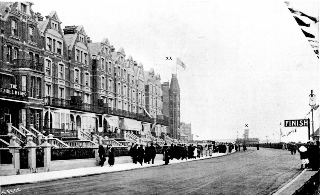 This view shows the track between the finishing point and the Chalet X, and also the curve at this part, and the unfortunate fact that the camber of the road is in the wrong direction, so that any tendency to sideslip is increased. X X is the tower of the Hotel Sackville. The track, which has an excellent graveled surface, is well-made and well-drained, and although it is somewhat heavy when thoroughly wet, yet the chances of side-slip are very small. From the top of Galley Hill, in the direction in which the cars ran, there is a descent of some 160 yards, which has a gradient of about 1 in 12. This hill not only enabled the competing vehicles to attain a fair speed before passing the starting line, but added considerably to the interest of the races, owing to the fact that he starting cars, with their white number cards in front, were visible to the majority of the spectators along the entire route, and that they're first down the track could be watched from a distance. The descent is not sufficiently long to enable cars to attain full speed before star the kilometer course, and some allowance must certainly be made for this when considering the results. From the bottom of the hill to the Sackville Hotel is comparatively level and straight, the one apparent curve being, in reality, more a deviation of the footpath and railings than of the road itself. The Sackville Hotel the road curves considerably to the finishing point, and it was this portion of the track which caused a certain amount of anxiety to the officials and the competitors before the event. In reality, the curve did not appear to present any element of danger, although it is probably that many of the speeds recorded are less than they would otherwise have been if the roads had been straight at this point. Those cars which travelled over it at a high rate of speed showed no serious signs of sideslip, although several drivers slackened speed perceptibly before taking the curve. The finishing point was about 220 yards from the gates which separate the private road from the town, and this was at first thought to be somewhat too short a distance for the fastest vehicles to pull up in, although, as events showed, the distance was in most cases sufficient. The one drawback to the Bexhill meeting was the weather, and this was a serious one. Rain and hail storms, strong winds, and cold air prevailed during the greater part of the Whitsuntide. Even during the bright intervals greatcoats and wraps were necessary for comfort. On Saturday and Sunday, a considerable amount of rain fell, and a very strong wind was blowing from Beachy Head. On Monday it veered round to a more northerly direction, growing at the same time considerably colder, and becoming less useful for drying the track. AMJ 24.05.1902. P.140. 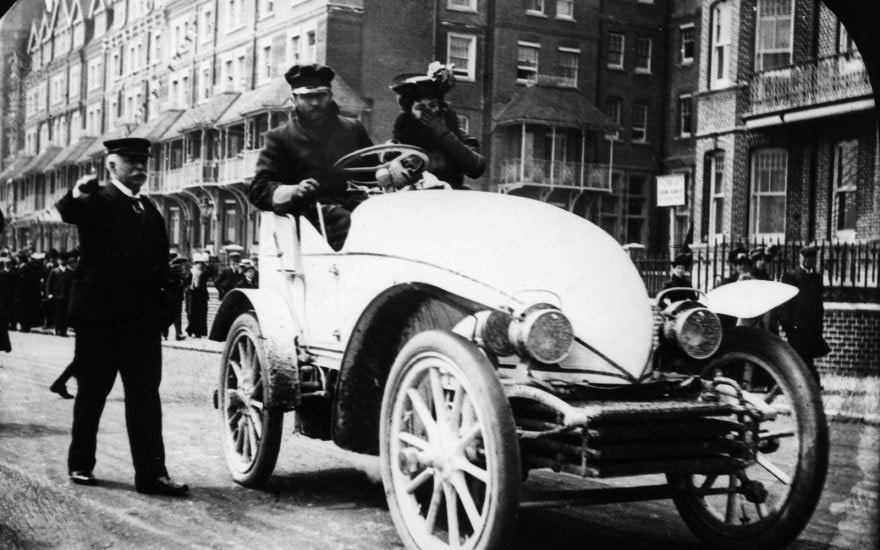 Arrival Leon Serpollet and his wife in Bexhill 18.05.1902 in a new racing car. The headlights and condenser tubes underneath will be removed before the race to make the vehicle lighter. Leon Serpollet and his wife arrived at Bexhill 18.05.1902 on the new racing car Gardner-Serpollet 120 break hp (bhp). This car was longer than the Nice race car. External differences are also another front fairing near the springs, triangles on the doors, a wider seat. Weight was less than 1000 kg. The competition began on Monday 19.05.1902 with paired races of cars from the Tourist section. In the steam car category, A.J.Dew won with a Gardner-Serpollet 6 h.p. with a result of 48.2 seconds. MCJ magazine estimates the actual capacity was 20 b.h.p. The tourist races had been enlivened, it may be added, by interludes on the part of M. Serpollet and Baron Henri de Rothschild, who were allowed to make trial trips with their respective racing cars before actually competing. The whizzing flight of M. Serpollet's car startled the crowd considerably and was the first intimation of the live lier performances that were to be expected from the races in the speed section (The Car 28.05.1902).time he sped past on top speed state, were let for the purpose. " (AMJ 05.24.1902). However, despite the fire, Serpollet showed the absolute best time to travel a kilometer in 41.2 seconds, which corresponded to a speed of 87.79 km / h. The Gardner Serpollet car, which set a speed record in Nice and was unofficially named Easter Egg, was sold in England for 55,000 francs. This car was shown at the the auto show in Agricultural Hall and then sold for 80,000 francs (Automobile Topics. 10 05 1902). The new owner was Mr. Creyke of Oxford. Mr. Creyke arrived in Bexheal in this car. He lent his car to Leon Serpollet to re-run after the fire of a new racing car. But the results of the re-run were worse, only 43 seconds. Therefore, the official result was the time it took to travel a kilometer on a new car. Second place in the Speed section category steam cars was taken by L. Perry-Keen in a Gardner-Serpollet 6 h.p. - 57.6 seconds. 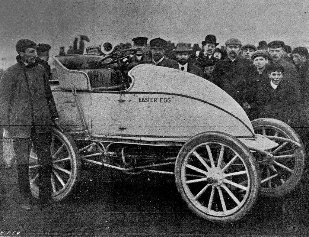 Mr. Craik and his car in Bexhill. The inscription "Easter egg" appeared already in England. Thus, Leon Serpollet participated in the same competition in two different cars, which, since 1902, were often confused in the press 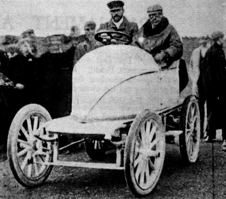 .Leon Serpollet and Mr. Montague pose in Mr. Craik's car.
I, Vasily Shishka, am writing the book “Cars of Leon Serpollet”. The main consultant to this book, as well as the initiator of its writing, is Chris Wedgwood, a man with steam in his blood, a steam engineer and car restorer. Chris and I spent many evenings chatting, trying to figure out the different nuances of Serpollet cars. The second consultant is a wonderful French archivist, author of books on the history of French motorcycles, Didier Magister. Invaluable help is provided by people from different countries who collect important information bit by bit: Alexander Kulchitsky, Dan Soudey, Davide Grappolo, Henk Schuuring, Thomas Ulrich, Umberto Voltolin, Fred Korthals, Daniel Ward, Tobias Ward, Goupil Dubois, Pierre-Jean Desfossé, Pascal Le Poder, Laurent Zoller, Michael Hortig, Jos-Pierre Wantz, James Wood, Stanislav Kiriletz, Rustam Bikbov, Ivan Ponomarenko, Davide Lorenzone, Bocha Balboni, Alekse and etc. Thank you all so much! We ask for help from all people interested in preserving the global automotive history in the form of digital copies of brochures, family photographs and instructions for using Serpollet cars. The history of the Grout automobile and the family isn’t in any one book, yet. All of this information I’ve collected from sources like original motor journals, vintage car club news letters, local news papers, online searches, and the helpful Walter Pollard. There are quite a few discrepancies in facts collected like were there 3 or up to 6 brothers? I’ve done my best to leave the conjecture to what lead to the company’s demise. What would eventually become the Grout Brothers Automobile Company was established in Orange, MA, USA in 1896. Fred, the eldest of the brothers, was the mechanically minded of the brothers and with a 3 man team, built an opposed cylinder internal combustion auto in 1896. His brothers Karl and Charles joined the effort, and they made about a dozen cars between 1896 and 1898. He switched to designing steam wagons in 1898 after his I.C. vehicles proved to be too heavy for the power produced, and the carburetors were prone to fire. Their efforts finally proved enough for their dad, William L. Grout, to join, help organize, and expand the company. The father funded the brother’s endeavors with money made chiefly from his New Home sewing machine (over a million sold annually in the 1890’s), as W.L. Grout was quite industrious, a multi-patent holder, and a friend/rival of Mr. White (also of sewing machine and automobile production). It was his industry that brought the family to Orange, MA as the town was well supplied and situated for manufacturing. The first purpose built factory for automobiles was opened for the Grout Brothers in 1900- it still stands and is a tire warehouse. 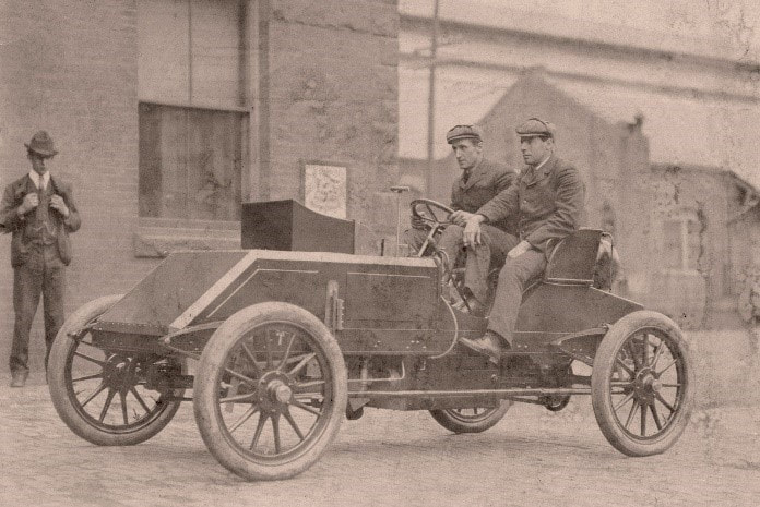 Speed trials, fuel economy trials, hill climbs, and auto shows garnered the Grout autos great esteem with many 1st place prizes in the states 1903 race with the Stanley Turtle, a bent rod sent them home and the racer was disassembled. Grout produced fire engines and work trucks they called steam wagons as well as automobiles for pleasure. The driver of the steam wagon sat on the boiler, with the engine placed midway back and wheels driven by countershaft chains. A 1904 Grout Steam wagon is the oldest known truck pictured to haul an automobile in the USA. Grouts used their wagons to deliver their vehicles to nearby buyers or to the train, keeping their delivered product perfectly clean. By 1905, 125 men were employed and continued to produce “thousands” of Grout Automobiles if their ads are to be believed. Thomas Edison was one of the first to purchase their new gas models after a tour of the expanded factory August of 1905. 1903 was the last year of tiller steer, and 1906 was the last year for steam power. 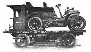 There are no records surviving of how many cars the Grouts actually produced before their closure, but there is remaining hearsay of how the company met its demise. Family funding means family expectations and the younger brothers held onto Fred’s coat tails, becoming less and less helpful and more about having a good time as the company progressed successfully. A car went for a river swim during a delivery. A unnamed Grout brother in charge of delivery stopped for a drink at the pub, filled with liquid courage, he took a lady for a quick spin and went too quick for the turn before the river. Perhaps that’s why they implemented the steam wagon delivery. Charles and Karl made the family drama more public, going to court in 1907 against their 73 year old father who was trying to take management control, he didn’t like how the company was being managed and they claimed his second wife wanted more money and was taking advantage of his failing mind. The brothers were appalled when they each were willed $5 after their millionaire father’s 1908 death. Their stepmother refused to “fund their playtime” and pulled out all the remaining financial support that their father left standing. The brothers left the company and town, and the company met a steep decline, falling into receivership and multiple changing of hands before finally folding in 1912. The family sold any remaining holdings with the factory buildings auction in 1913, and the last mention of a Grout automobile being produced is 1915. The brothers had short lives, possibly due to tuberculosis. Fred died in New Mexico in 1909. 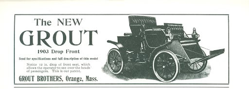 Tilly, a 1903 model J drop front is an example of the Grout Brothers’ abilities during their most productive years 1900-1904. The earliest mention I have found of our car is a 1941 Wolfeboro NH article about three local young men collecting and restoring old vehicles. Harry Hopewell had what he then believed to be a 1905 Grout steamer in storage in his Newton MA home. The only clue we have of Tilly’s original owner somewhere in Maine is the story given at the discovery purchase. After a particularly bad day of learning to operate her new to her car, the lady of the house was on the last leg of the drive and ran over her neighbor’s cat. Distraught, she parked the car at the back of the shed, where it sat, behind a wood pile, until Harry bought it. 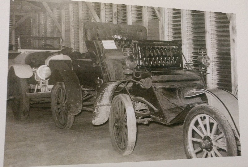 After the war, Tilly was placed on display in Mr. Glen Gould’s Shirley Auto Museum where it sat, a bunkmate to a 1904 Grout that participated in the 2010 LBVCR, unrestored and un-operational until 1967. Tilly was part of a group lot my father-in-law, Frank Cooke, purchased from Harry who by then had decided that the year was more likely a 03 or 04. The license plate numbers inscribed on the lanterns are assumed to be the culprit of the 05 dating as Maine issued plates starting in 05. That’s a whole new rabbit hole to explore as the scribbled numbers in our oldest known photo are a 33? 55? 88? The only combination that works with the license registry is 85, to a Theodore Davis of Portland with a 4hp Grout. Satellite map imaging show his listed address is now apartment buildings, so I can’t confirm the story by building placements. Further research is due. 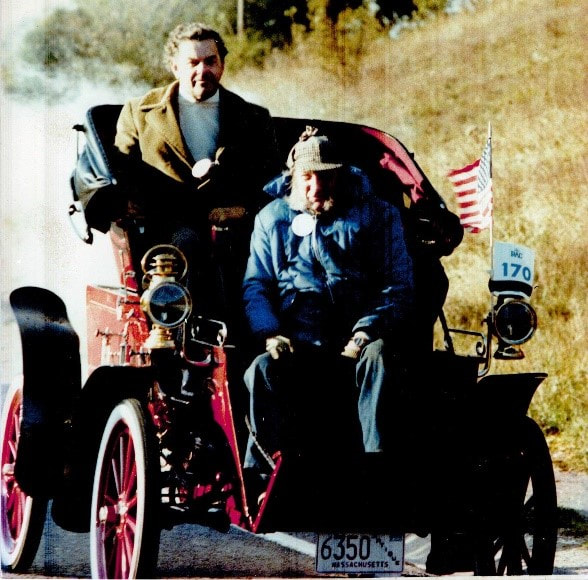 Frank got the car operational but not restored in any way and had it tooling about locally before deciding to ship it over for the London to Brighton run in 1979. It was a failed attempt stopped at Worthing with further injury as the bypass was closed during towing, causing great engine damage being pumped full of water. The Brighton and Hove Engineerium took custody of Tilly and not only repaired but repainted it, leading to a successful 1980 and 81 L to B run. The 81 souvenir program has a cute note. “ Grout- American steam cars, Frank Cooke of North Brookfield, Mass. (USA) has taken part in the run these past two years with is 1903 car but E. Frank Taliaferro, from San Diego California, on the West Coast is in for a shock when he arrives with his 1901 Grout for the first time. On his entry for he stated, “Only Grout in running condition in existence (to our knowledge)”. Mr. Taliaferro me Mr. Cooke...(no’s 88 and 185)” Mr. Taliaferro had a 7hp surrey. Tilly came back to the states and took the long-term mantle of the only reliably running Grout in New England until the early 2000s when Frank and his son Billings (Bill) decided to upgrade the original burner and replace the boiler as the car simply couldn’t produce enough steam for continuous driving. Frank passed in 2005, and Tilly went into storage incomplete. 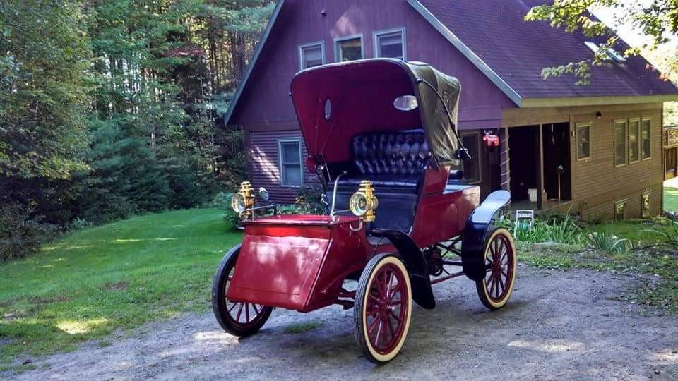 Tilly was brought out of storage with an invite to the 2013 Boston Cup as part of their Made in Massachusetts highlight. It received the people’s choice award; Bill received the gumption to get it running again. Storage was not friendly to Tilly. The original wood body had developed a sway back and several structural cracks that were unsafe at any speed, forget the weight of a bigger burner and boiler. Starting in 2016, M.S. Herman & Co did the body dismantle and restoration, while Bourdon Boiler Works built a new copper water tank to go along with the previously made burner and boiler, and Rempco rebuilt a newly acquired Grout engine replacing the small engine (not Grout) used for the 1979 repair. Stutzman Wheel shop made four new wheels. Randy Beaudoin of North Country Signs gave a color match new body and wheel paint and Kenny Jacobs did the gold-leaf and pinstripes. The seats are still in good condition and received conditioner only, but moths got to the flannel lining of the top. Mike Lemier of Richmond Upholstery repaired the lining and reset the glass windows. 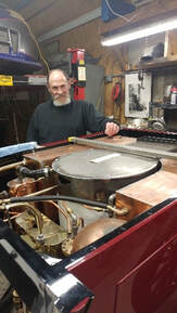 The rest of the reassembly happened at home, and I assisted where possible. Trying to improve the brake system proved problematic. Tilly had only one brake drum and shoe on the differential as originally constructed. The construction of the differential offered the opportunity for a second brake setup. Frank added the necessary components to have a shoe on both sides of the chain sprocket. He used a cable and pully balance system from the brake pedal as the original brake rod path passes above the chain sprocket on the engine and is tight for two rods. Bill kept the two shoes and upgraded the cable system to two rods with a balance bar near the brake pedal to balance the pull on the two shoes. This still just slows us down, not stop. We’re still playing with brake lining options, hydraulics are a future possibility. The other brake project is to make a parking brake, as the hills and mountains of Vermont have few flat spaces.  A pilot tank was added, as the Grout originally ran a single fuel tank with both burner and pilot running on gasoline. It was mounted beneath the front passenger seat, out of sight. The new Stanley style pilot is now fueled by coleman fuel, the original pilot was comparable to a miniature blow torch and lit “with a single match”. The first firing was in May of this year. Growing pains started not long after, as on the second run we (with me driving) plugged our boiler sight gauge with mud we’re still blowing out of the boiler and had a small scorch in our driveway. Time sitting wasn’t good for the inside of the boiler, we still have no idea what actually caused the mud to build up. But Tilly likes to sing, and we’ve been back out on the road a couple more times. Definitely miss those club meets, gets us out of the house and our cars on the road. And we’re currently installing a second boiler gauge of David Nergaard’s design. It’s similar to a Bristol Derr water gauge, so a bit higher tech but also camouflageable, it won’t stick out like a sore thumb. The sight glass only gave us the bottom third of the boiler, this new gauge will give us readings from empty to full. 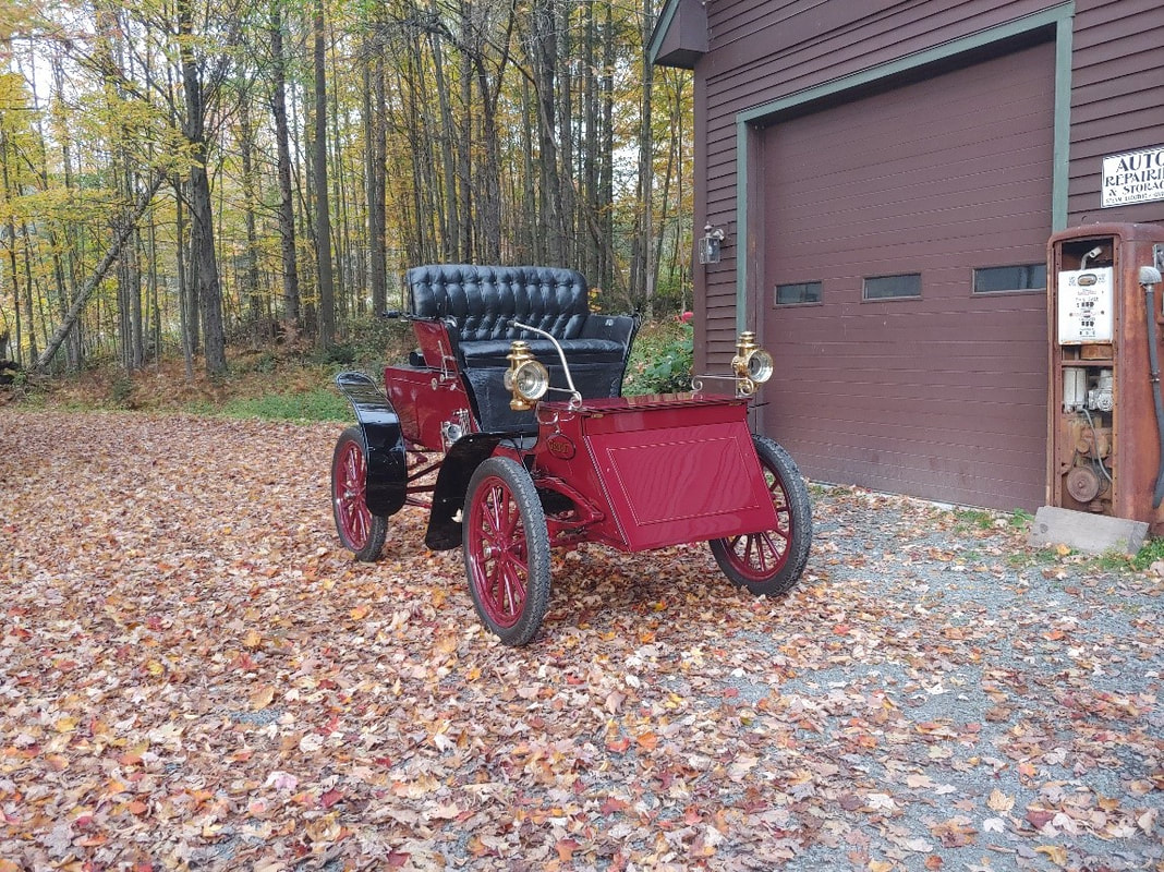 The top never had a boot for it’s down position, Frank lashed it down with straps for open trailer towing. This is my winter project, to build a boot or two for Tilly. I’ve got enough material, there might be a bag for onboard tools as well.
2020 was supposed to be Tilly’s grand debut at the Eastern steam tour, which we were also hosting in Tilly’s old stomping grounds in central Massachusetts. That has been optimistically rescheduled to June 2021 and we hope to see our small and large horsepower friends again. We also want to spread the word that the Orange Historical Society would like to know who else has a Grout, Mr. Pollard is the lead Grout historian there. There are currently about 30 known steam-powered Grouts in the world and no internal combustion Grouts. Mr. Pollard is writing a book about the Grouts and their company, spending the last 25 years on research. He can be contacted directly at [email protected]. Sarah Moon |
Archives
December 2022
Categories
All
|
 RSS Feed