|
Steam Car Network
|
|
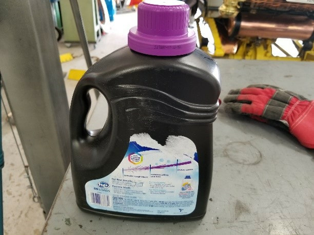
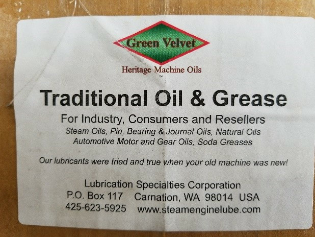
1909 Stanley Steamer Model R Service Manual and Maintenance Log WRITTEN AND PRODUCED BY Herb de la Porte Part One 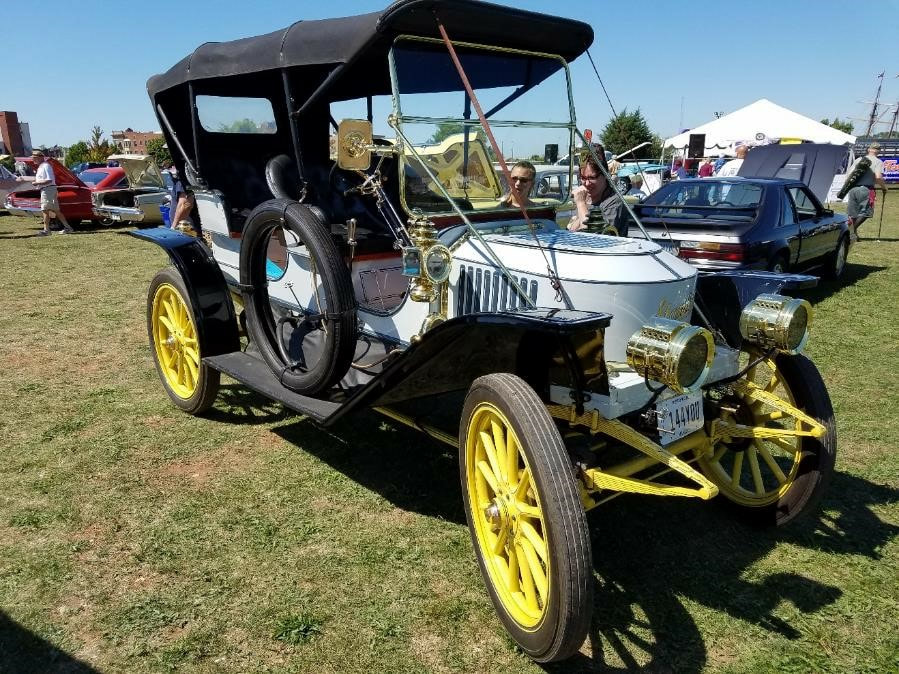 History: This car is a re-creation by Basil Craske from England that started with an Alan Kelso project body. Basil Craske Bought the body in Ireland in 1999 and recreated the car around it in time for it to be shipped to Australia in the early 2000’s for their inaugural steam car tour. Sold it after a number of tours to Phil Lewis of Cleveland in 2006 while on a steam car tour in the Ohio area (Berlin). In 2013 Phil Lewis sold the car to me along with a new Baker style Burner delivered by Allan Blazik 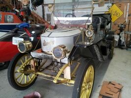 By the time I got the car, Phil had taken it on a number of tours and it had not ran very well for a while. He was well into his 80’s and crawling all over the vehicle became impossible. The brass had not been polished since 2006, the burner had warped and cracked due to serious undetected back fires and everything else performed very much sub-par. The Contents of this part of the story are as below Basic Operation. Water System.. Oiling System.. Oil Pump Operation. Check Valves in the water system. Blow-down and Siphoning into boiler after cool-down. Steam powered Siphon. 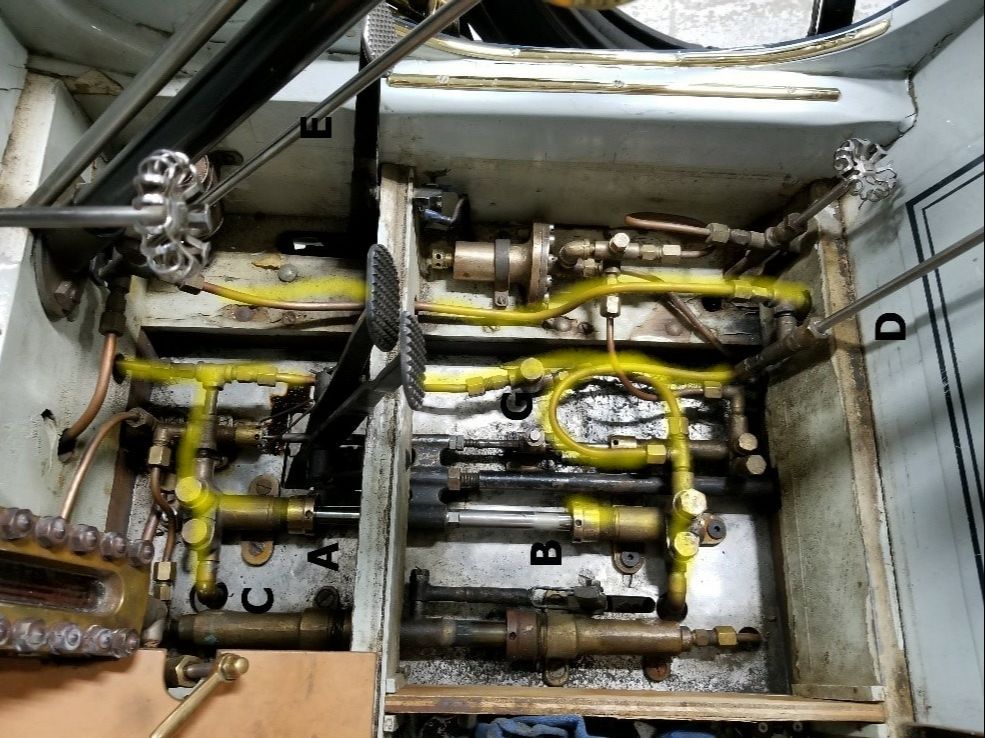 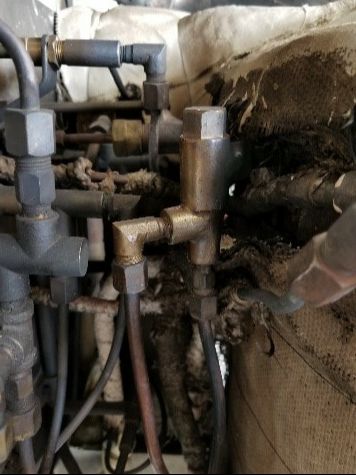 The Water system takes water from the reservoir under the seat and pumps it into the boiler. Water quantity is adjusted by two valves. The one on the steering column is the on-off switch for everything. Closing the one under the seat under the seat (highest Valve) adds the second pump to the mix 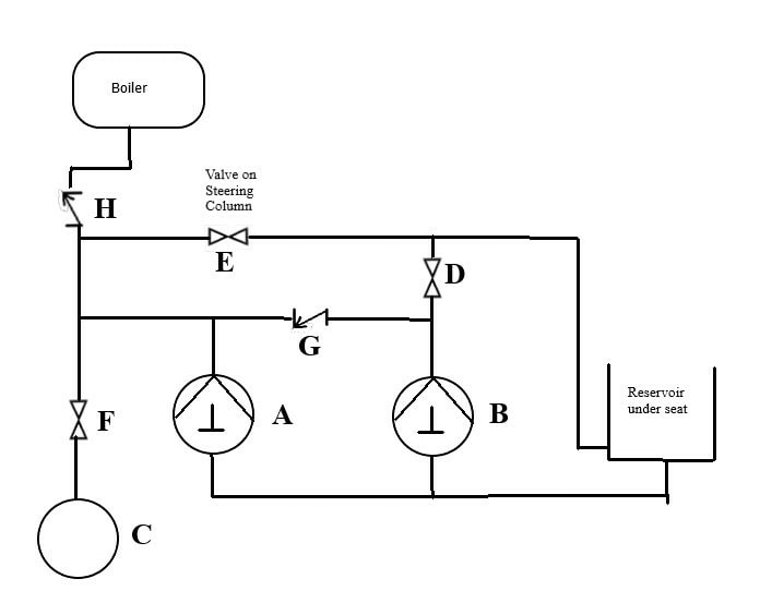 When the wheels are turning and the boiler is pressurized, one-way valve (H) is closed with up to 600 psi of pressure. When both valves (D E) are open, water meets resistance at (H) and flows back into the reservoir. When you close valve (E) on the steering wheel, water from the front pump, unable to pass through (G), builds up enough pressure to overcome the boiler pressure and flows through (H) into the boiler. the rear pump still flows freely back to the reservoir. If you also close Valve (D) water from the rear pump will no longer be able to go back to the reservoir and is forced through the one-way valves into the boiler as well The manual handle has the option to add water to the boiler by opening valve (F) under the floorboard and closing the other valves. When doing so, you’ll suck water through the main pumps one-way valves and push it through the system that way. The volume amounts to no more than a couple of ounces per stroke. Since there is a sizeable amount of pressure to overcome when the valve is open, for routine operation it is advisable to close the valve while the pump handle is as far forward as possible or you won’t be able to manually pump fuel. The manual handle has the option to add water to the boiler by opening valve (F) under the floorboard and closing the other valves. When doing so, you’ll suck water through the main pumps one-way valves and push it through the system that way. The volume amounts to no more than a couple of ounces per stroke. Since there is a sizeable amount of pressure to overcome when the valve is open, for routine operation it is advisable to close the valve while the pump handle is as far forward as possible or you won’t be able to manually pump fuel. Oiling System The Oiling system is a brilliant design in simplicity. There are no check valves and the gauge is a disk pressed against a window by a spring but the system requires some care in setting up 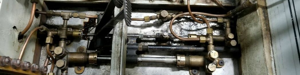 The oil used is a 1000W mixed with animal fat. It has to be formulated for the higher pressures a steamcar runs versus a locomotive or steam tractor. Condensing cars are even worse as they need an oil that can be removed from the feedwater before it hits the boiler again When oil gets in the boiler, it coats the insides, creating an insulating barrier and requiring more heat and, therefore, more damage. Condensing boilers tend to have a shorter life span then non-condensing boilers I have been using Green Velvet products from Bill Petitjean. Bill’s oil is very dark and seems to stick to everything. The best way to dispense it seem to be through a laundry detergent bottle with a big spout. In 2018, bill sold the green velvet line to Brennan oil in Durango, CO 970-247-3054
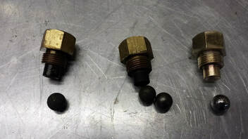
Oil Pump Operation An ingenious device. It is adjustable to give a metered quantity of oil with every stroke the concept is simple. There are two pistons in the pump. The one on the right is connected to the drivetrain and the one on the left is held in place by a spring 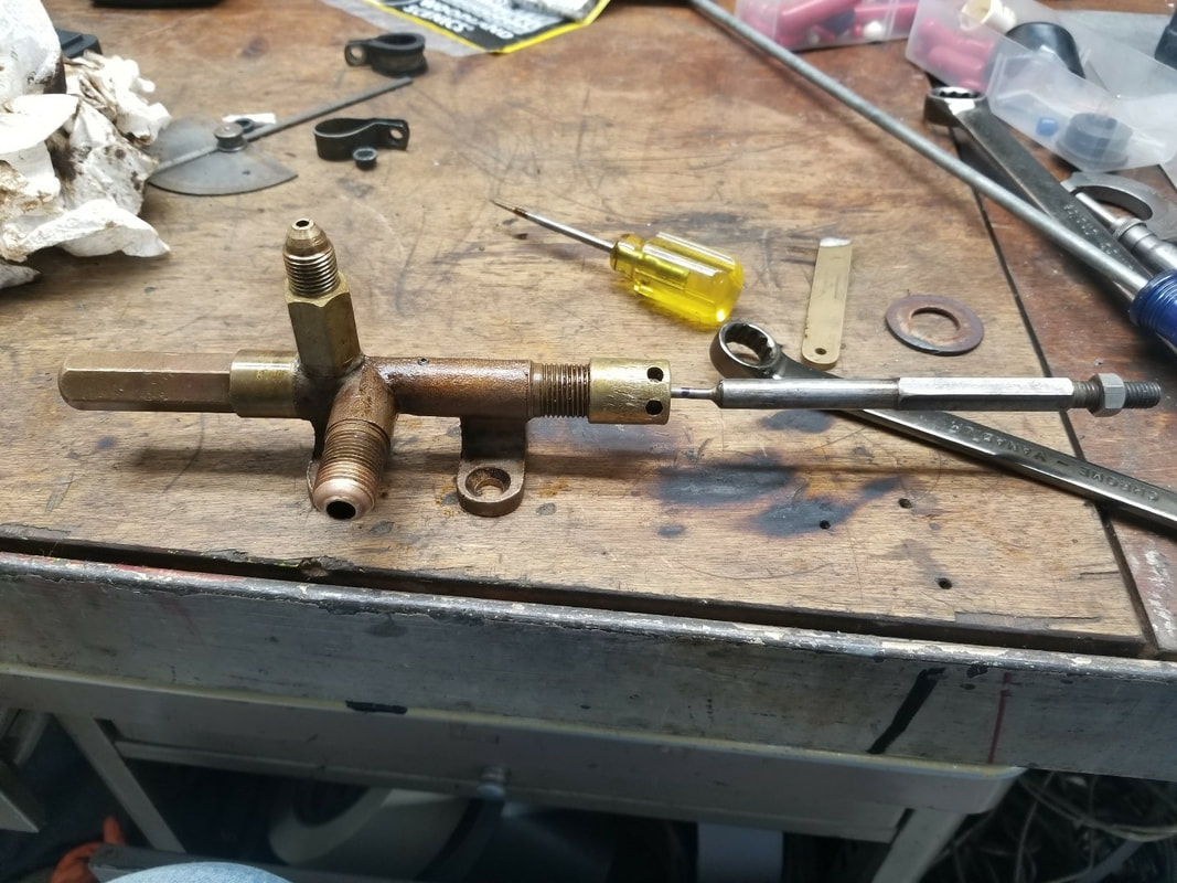 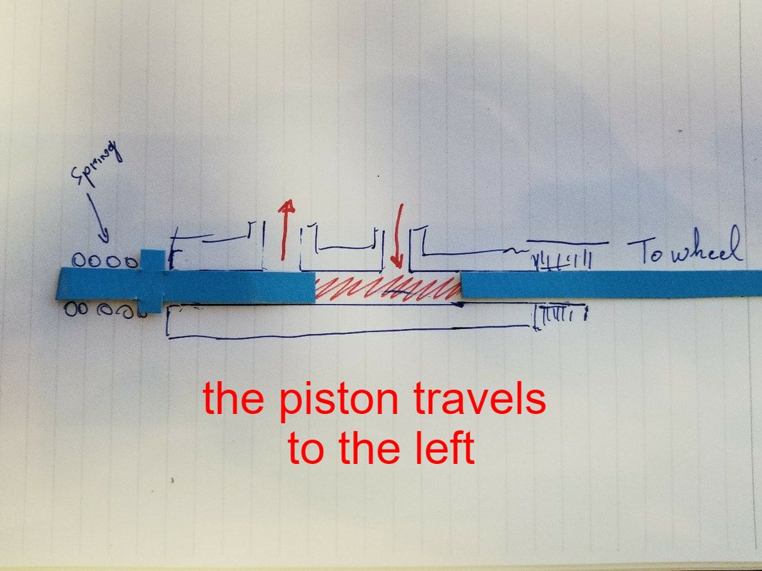 When the driven piston is the way out, oil can only come in through the inlet 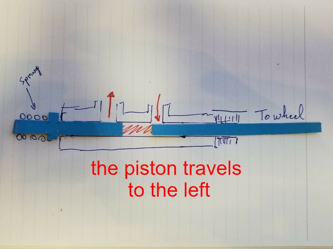 As the piston moves in past the inlet hole, the reamining oil has no easy outlet and starts moving the left piston 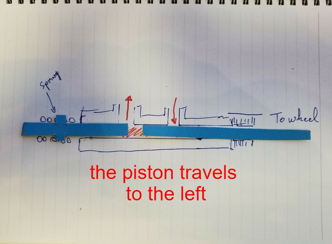 Once the left piston gets to the outlet hole, the oil escapes 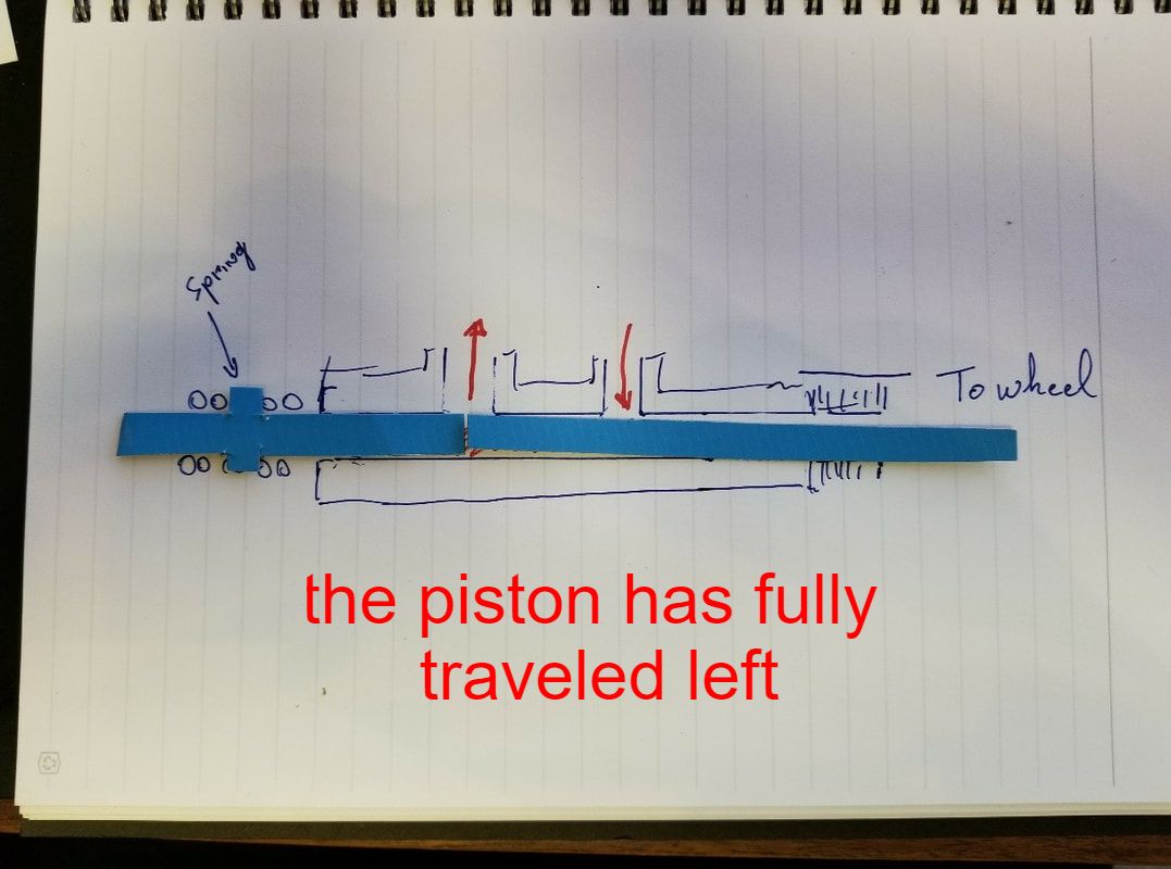 Until the entire metered amount is gone. When adjusting the piston, it is important the driven piston cannot go further than this position as it would try to press oil in a closed container 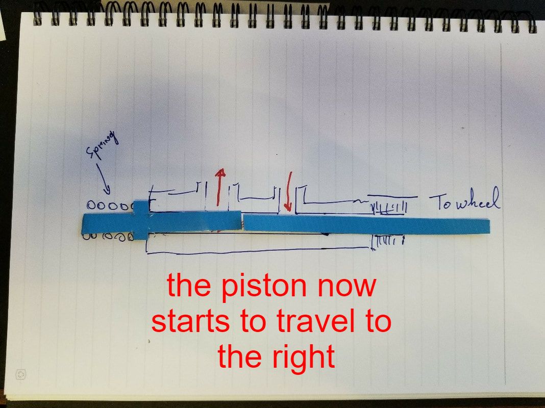 As the driven piston is pulled out, the secondary piston stops at the preset area 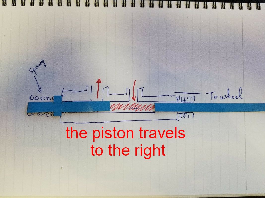 The vacuum created at this point helps fill the reservoir up again for the next stroke The actual pump and metering rod looks like this: 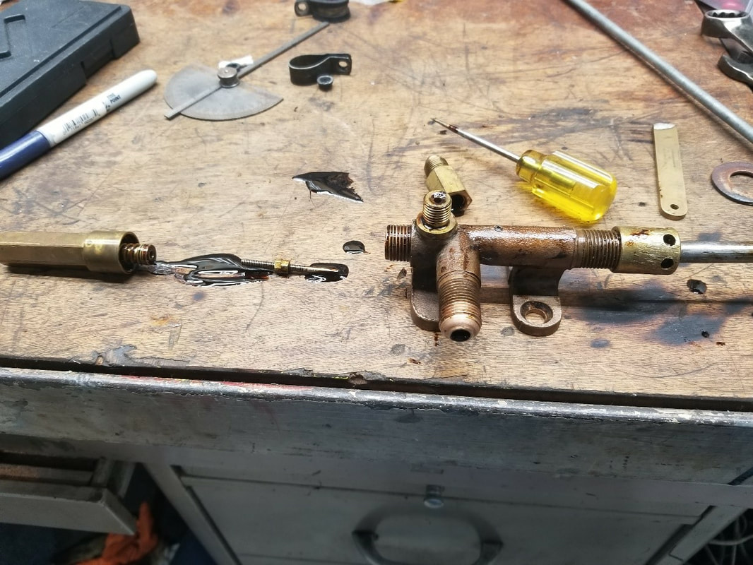 Adjustment details are in another section 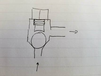 There are a number of check valves with two in each of the main pumps, one between the pumps and one at the boiler The ball is held in the assembly by a special screw that allows the ball to travel about 1/32” The balls in the pumps as well as the check valve below the floorboard are 7/16” Delrin. The one in the check-valve at the boiler is stainless steel Delrin is preferred as steel would eventually hammer out the seats. Obviously that material cannot be used In valve (H) as the heat would destroy it Since the balls deal with pressures in excess of 600 psi, replacing the delrin ones annually is probably prudent. The boiler valve should not be touched until it leaks, which is characterized by steam pushing into the reservoir
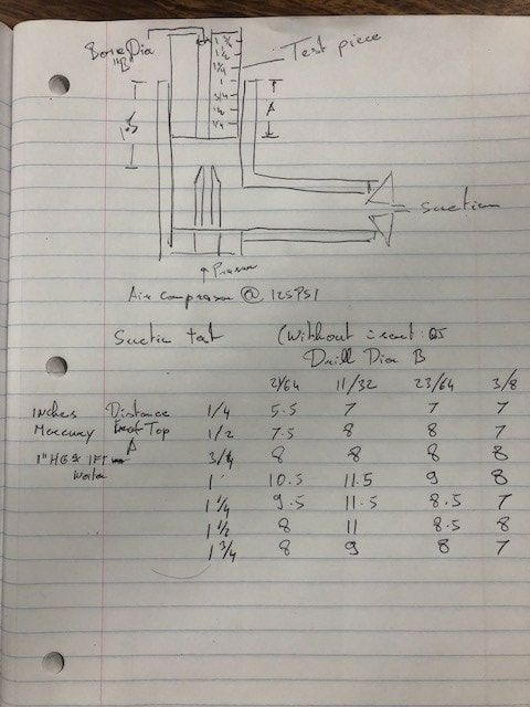
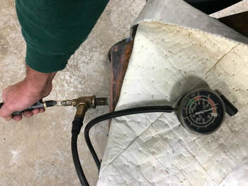
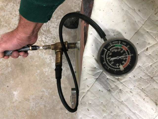
Blow-down, other than a great piece of entertainment or annoyance, depending on the neighborhood, is crucial to get sediment out of the boiler. Each corner of the boiler is connected to a valve on the front of the car. Try to blow down as soon as possible and at as high a pressure as possible after every run to avoid stuff to settle. The purpose is to get as much crap out of that boiler as possible. Make sure the pilot is out and no fuel can go to the boiler before blowing down. This is an extremely loud event. Wear Ear protection and turn off the hearing aids The water in the boiler at 600 PSI is roughly 500 degrees Fahrenheit. When you let it escape, it will turn to steam instantly forming a characteristic tulip shape at the nozzle. Open all four valves three full turns. Let the steam escape until the steam shape turns from a “Tulip” to a straight flow. Close the valves as quickly as possible. You should still have around 400 PSI remaining which will allow you to park the car.  The steam coming from the nozzles will be cool enough within a few feet that you should be able to hold your hand in it for a short time. It’s a great way to see how filthy the water in the boiler gets 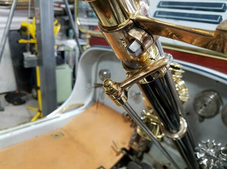 Before the boiler cools down, Make sure the throttle is completely closed, fill the water reservoir and open the water valve on the steering column. As soon as the boiler cools below boiling temperature the remaining steam will condense and the boiler will become a vacuum chamber. Opening the return valve may help give water a little less friction on the way to the boiler. Storing the boiler full of water limits corrosion and extends its life The Stanley has a steam powered system to suck water from below the level of the vehicle and pump it into the reservoir. The system works by sending a jet of steam through a ventury and creating the vacuum needed below it to suck up water. Once cold water hits the nozzle, the pressure of the steam will still shoot it upwards, keeping the vacuum below going and most of the heat will be absorbed by the water on the way up the tube I am spending a bit more time on it here because these principles also apply to the way fuel and air are mixed in front of the burner 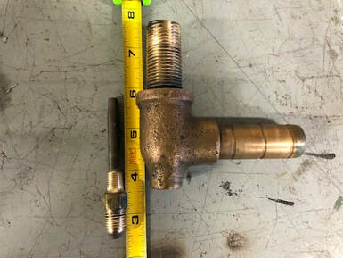 The simplest way to explain the principle is that the steam velocity from the tapered pipe on the left creates a vacuum right around it. In order to get the ultimate in suction, however, the nozzle and tube around it (ventury) sizes are relevant to each other. if the ventury is too big, air will be allowed to leak back out. The basic suction system in the model R is to the left. It was screwed into the tank where it ended into a 3/8" ID tube leading to the top but the nozzle was placed in a 2" section of 5/8" diameter tube. It never worked well so i made a test rig to see how much it could be improved upon by turning piece of 5/8" plastic, notching it at 1/4" intervals and increasing hole sizes during the tests
The results surprised me in how little it took to get major changes 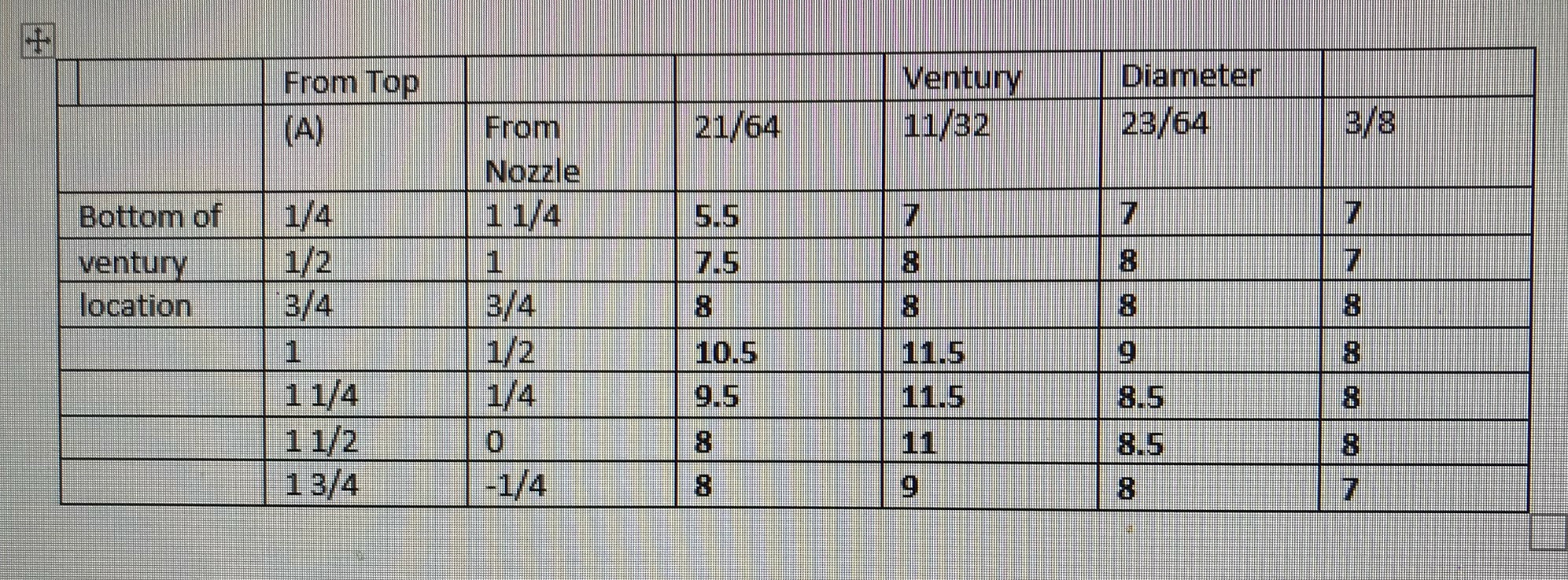 lessons learned: 1/64" diameter makes a difference. The "Sweet spot" appears to be for the restriction of the insert to start about 1/2" above the nozzle another test piece at (A) 1 1/8" with a 11/32" diameter able to be screwed into the tank showed that there was a marked improvement in Suction
since Mercury is about 13.5X heavier then Water, a conservative estimate would be that every inch of vacuum should equate to about a foot from the bottom of the tank.
0 Comments
|
Archives
December 2022
Categories
All
|
 RSS Feed