|
Steam Car Network
|
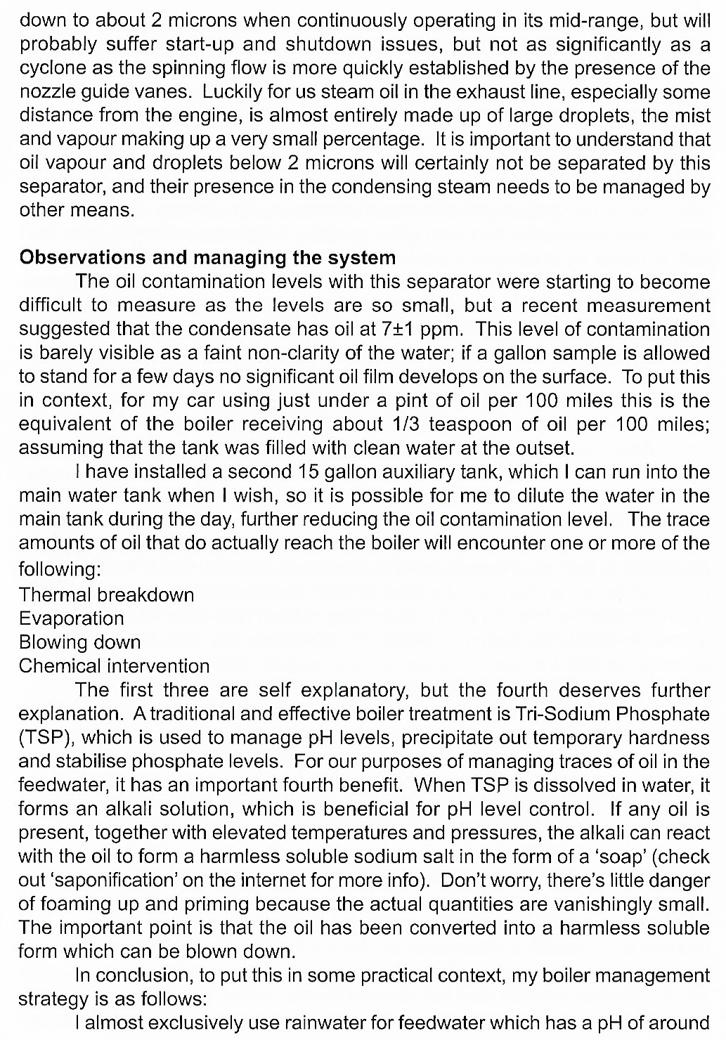
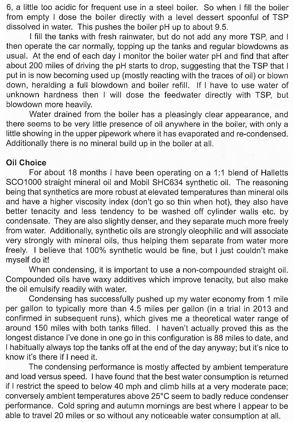
400 Miles By Stanley in One Day3/8/2021 Reprinted from Light Steam Power including Steam Power Vol.XXVII No.I. This was not a publicised endurance run organised for publicity at a time when these American steam cars were being made. It was completed in one day in September, 1977 in England, from the Midlands over notorious Shap Fell into the mountainous North West. Though the weather forecast was "unsettled" and rain had not helped the pre-run steam up the night before, Friday, September 2nd proved mainly fine but chilly- just as well for P.D. Stevenson's Stanley 740 is as yet without windscreen, hood, or even side doors. The sparse plywood side sheets gave little protection to driver and passenger, A. Ritchie, who also owns a Stanley. The fitting of a windscreen has now been given top priority. 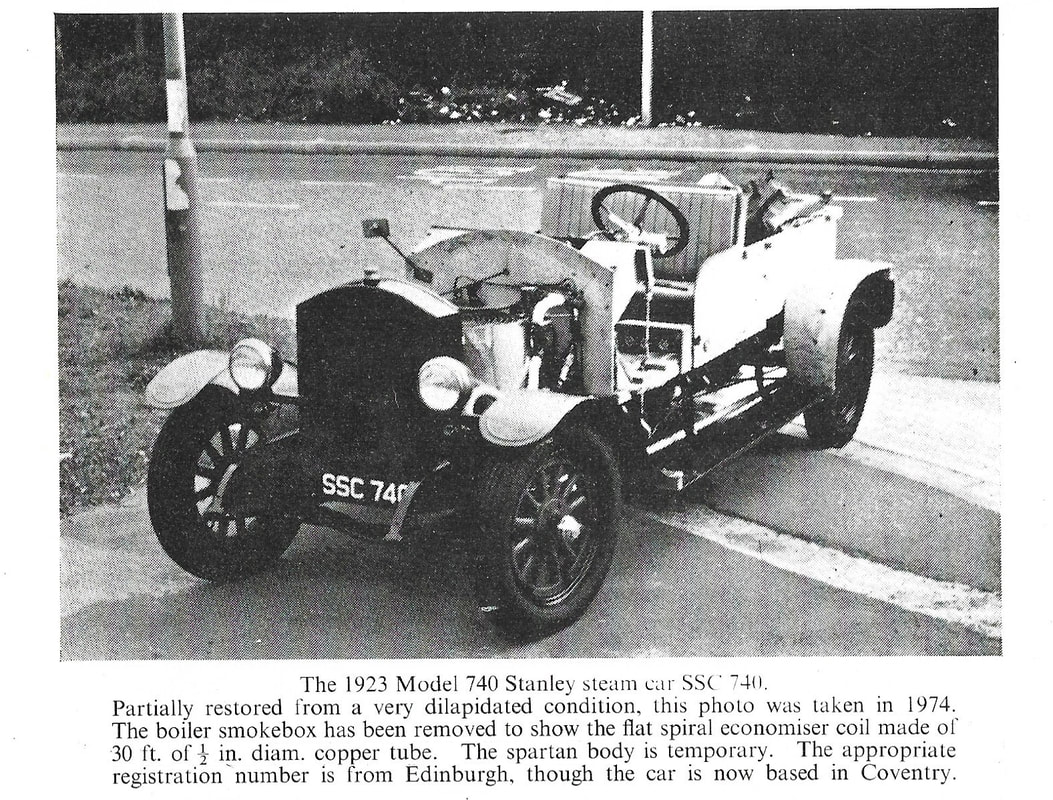 With the steam car's pick-up style rear compartment well stocked with containers of paraffin, a fuel very scarce on British motorways, the party steamed away from Coventry at 4am all set for Penrith, Cumbria. Showery weather improved to fine later. Unfortunately burner trouble was to plague the crew, causing about ten stops in the first 200 miles. The original Cruban burner was suffering from low fire caused by carboning up in the vapouriser. The consequent shortage of steam was eventually cured by removing one of the eight strands in the burner vapouriser cable, thus allowing freer vapour flow. Thereafter the old car maintained steam pressure at 400 to 425PSI at 40 to 45 MPH with 500PSI available for startling acceleration in towns, at which pressure the main burner cuts out automatically. Below 40 MPH the flame dies down and restarts under automatic control. Condensing in the large fanless Stanley "radiator" is usually complete, though at about 25 MPH up the long windswept hill over Shap caused an occasional wisp of steam. About an hour was used for completion of some fortuitous business en route, before arrival at the market town of Penrith, which is not very far from the Scottish border. Here four or five hours included a run around the town and its environs with a friend, who had owned a late model Stanley many, many years before. The return journey started at 1.a.m. the next day, when a squall was soon left behind. Burner troubles having been cured, the Stanley proceeded in fine style at 40 to 45 MPH on its return to Coventry with steam pressure carefully kept above 400 psi, which at cruising speed drops to 125PSI at the engine steam chest. This time more than 120 miles were completed without a stop, allowing full enjoyment of the exhilarating silent travel by the spartan crew. The new parallel flow superheater, which maintains steam temperature at 716 deg. F. (380 deg. C.) at a steady 40MPH gives considerably improved running with economies in fuel and water consumption. Only 5 or 6 gallons of make-up water were needed on this return trip. The old zig-zag superheater would only maintain 572-617 deg. F. (300-325 deg. C.) in the same driving conditions, which caused a relatively sluggish engine. "Cylesso" cylinder oil is metred into the steam line at the rate of about 1 gallon per 1000 miles. If steam pressure drops below 400PSI fuel consumption increases noticeably and performance goes down. Throughout the whole journey there was no mechanical bother. Automatic control of water level and steam pressure behaved faultlessly and the troublesome burner settled down to reliable performance after the minor modification. However, this Cruban design does suffer from a red deposit on the slotted burner plate, the reason for which is difficult to find- does anyone have any ideas? Otherwise the car is stated to be almost trouble free. P.D. Stevenson intends to make many more long distance journeys in his Stanley, the first having been a long test run of 300 miles to Harewood House, Yorkshire, and return, which was accomplished successfully in September 1974. He knows his steam car is much more pleasant to drive than I.C vehicles, its quiet smooth power and high torque being especially appreciated. The speed is good for the roads of 1923 and later but more would be preferred on modern motorways. A maximum of 60MPH has been achieved for about 1 1/2 miles, but steam pressure was dropping. The specially allotted Edinburgh Registration Number SSC 740 is most appropriate. Not long before the Penrith run, I needed no second bidding in speedily accepting an invitation for an evening run on country by-roads. With the steam gauge needle hovering around 500PSI, the acceleration from rest was akin to aircraft take off- and all without apparent effort. There was no difficulty in maintaining more than 400 PSI with superheat along the narrow twisting roads again with no apparent effort in almost complete silence-a faint chuff chuff chuff being heard only when accelerating away from a stop. Therein lies the charm of these and similar steam cars. SSC 740 is claimed to be the only Stanley 740 in Britain. It is thought to have been acquired from France and possibly at one time owned by Ettore Bugatti of I.C fame, A saloon body was perhaps originally fitted. Since purchase by P.D. Stevenson in a very dilapidated state, the car has been stripped down to its chassis. The engine has been completely overhauled with cylinder bores honed 30 thou. oversize, new pistons made and piston rods hard chromed. A new solid shell firetube boiler has 636, 9/16 inch outside diameter (O.D) 16 gauge steel firetubes and steel tubeplates. The burner, steam stop valve and throttle valve are of Cruban design. 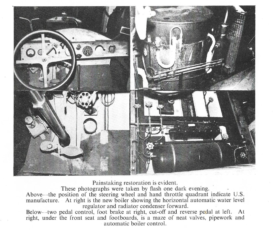 The unusual brake compensating gear is also believed to be of Cruban make. The steam pressure automatic is a Stanley. The exhaust steam circuit to the condenser includes a cylinder oil separator and a feedwater heater which uses 12ft. of 1/2 inch bore copper tube coiled inside a 6 inch diameter, 9 inch long cylinder. A flat spiral economiser coil of 30ft of 1/2 inch O.D copper tube is fitted inside the smokebox. The scanty temporary body will eventually be replaced by one of four to five seater open touring type.
Nearly all the work of this continued restoration is done by P.D. Stevenson himself, whose skill is more frequently applied to making specialised radiators for vintage cars.
0 Comments
Model F Doble. 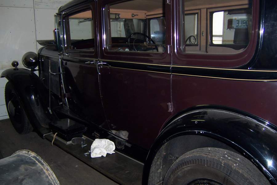 A few of the many photos Charlie Johnson sent of the work done on the Doble F. The car is still in the early stages of the restoration. we hope to bring you more as the work progresses. Recollections of my meetings with Abner Doble in 1930 As recounted to Bill Lloyd on 13 - 19 September, 1999 Athol Jonas Mt. Roskill Auckland 4 New Zealand My first glimpse of Abner Doble and E-24 I was born on 8th July, 1911 in Auckland, New Zealand. As a young lad in the 1920’s I had a keen interest in steam cars and had read of the legendary cars manufactured by Abner Doble in San Francisco. One day about 1930 I was greatly surprised to see one of these cars in Auckland city. It was parked on the northern side of Vulcan Lane off Queen street, just a stone’s throw from where I occasionally helped my father in his accountancy practice. I asked if he could photograph the car for me using his quarter plate camera and he did this on two different days with the car in the same place on both occasions. I often saw the car in the same area and in the same parking spot over several months. It was a pale yellow coupé with black mudguards and I noticed that the paint was blistered in a circular patch on the rear part of the front bonnet. The license plate was 8-341 and on another occasion 171031. The right hand window was partly down and a spectator once reached in and blew the horn. I was immediately interested in the instruments and noticed the steam pressure was reading 600 psi on a small gauge. I don’t remember the exact colour of the car interior but I do recall that the seat leather wasn’t black. To find out more about the car I got in touch with my cousin Charlie Jonas who was a mattress manufacturer with an office in Lorne street. He had built a small model steam locomotive and was active in the model engineering society. Doble attended an exhibition of this society and there is a photo of Mrs. Doble beside my cousin’s locomotive. He told me that Abner Doble was in New Zealand to supervise a joint venture with A&G Price at Thames for the manufacture of steam buses for the Auckland Transport Board and the White bus company at Thames. He also thought that Doble was importing the fuel for his car. It wasn’t running on petrol. It had a very distinctive and seductive odour of oil and steam that only a steam car can have. I believe it was running on diesel oil which was very difficult to get in those days. It was proposed to run the buses on diesel, which was much cheaper than petrol. Doble’s car E-24 was parked in a side road in the busiest part of Auckland and usually attracted a lot of attention. I always had a close look at the car whenever I could and on one occasion I saw a tall and distinguished looking gentleman getting into it. He had a fair complexion and was neatly dressed in city clothes with a felt hat. He was noticeably stooped for a young man of about 35 and I immediately noticed a conspicuous and rather horrible scar that ran diagonally down one side of his face. It came from eye level down to his jaw and looked like a bad piece of facial surgery that hadn’t been stitched. It was particularly noticeable on his rather pallid features. There were several theories - a far fetched one that it came from a sword duel but the more likely explanation subsequently given in an article in Light Steam Power was that it arose from a boiler explosion. I am a pianist myself and instinctively look at a person’s hands when I first meet them. I noticed that his hands were unmarked, not the hands of a manual worker. He had the hands of a musician rather than a manual engineer. I would have liked to speak to him but was only about 19 at the time and was too shy to approach him directly. Fortunately the opportunity arrived by accident a little later. On this first occasion I watched as he got into the car and I heard a soft, deep rumble as the burner ignited. A faint blue haze came away from under the car and left a delightful odour of steam, oil and flue gases. The car moved off silently, except that when it was about 20 feet away there was a sudden “crack” like the knock of a hammer on metal. Neither my father nor I knew what this was at the time but I now realise that this was one of the high pressure relief valves discharging condensed water from the cylinders back to the water tank. I watched with my father as the car moved away in almost total silence. I had just had my first glimpse of one of the most famous engineers of the steam age. Chauffeured by Abner Doble A little later I had the opportunity of meeting Abner Doble in person and riding in his car. I was in a garage in Chapel Square in Auckland city to see a home built steam car with a Locomobile engine owned by “Steam” Stewart. H.H. Stewart had been a joint agent with the Treloar Milking Machine Co which had been the sole or primary agents for the Stanley Company some years before. Stewart also had some connection with the Doble/Price venture and had received around £750.00 in commission for introducing Doble to Prices. I was chatting to Mr. Stewart and Jim Lawler the garage owner in the enclosed garage office when Abner Doble wandered in. He had parked his car in the street outside the garage and was apparently expecting to meet Stewart there because he said to him “I want to make an appointment with you for lunch.” After a little discussion, Stewart introduced me to the first American I had ever met in the flesh. I noticed his accent but nothing otherwise remarkable about his voice. It was average, unhurried but business like. He was neatly dressed in a business suit with his felt hat and was smoking a cigarette in a short holder, something I hadn’t seen before. He and Stewart spoke on first name terms and when Abner was about to leave I took an indirect approach and hurriedly asked Stewart “Do you think he’d give me a lift?” “Give him a ride!” said Stewart in a rather obliging tone, possibly using the opportunity as a convenient way of removing an over-enthusiastic teenager from the office. Doble immediately agreed and we walked out towards the car. But before we got there he stopped to look at the experimental steam chassis that Stewart had built and which was being stored in the garage. “I like the idea of your single spoked steering wheel!” he joked at the hasty construction. As I got into the right hand side of his left hand drive car I noticed a small white wire haired terrier occupying the shelf behind the single front seat. These were fashionable at the time and someone had given it to him as a present. My next impression as I lowered myself onto the single bench seat was something of a surprise when the cushion hissed at me. I had never seen a pneumatic cushion before. He switched on and we turned around. He had been parked on the “wrong” or right hand side of the road. The car moved to the end of the short Chapel Square with the Catholic church on our right and we turned left into Wyndham street, then eastwards down to Queen street where he turned right. He stopped some distance up Queen Street, on the eastern side, directly in front of what was then the Auckland Savings Bank and said “I’ll be here for about 10 minutes.” He then reached across me to shut the passenger’s window to prevent the dog from escaping and excused himself with the comment “Just so he won’t elude you.” I definitely remember him using the elegant expression “elude”. He went into the bank leaving me and the dog in charge of this remarkable machine. I was careful not to touch anything. He returned from the bank and we proceed up Queen street to the Wellesley street intersection, occupied by the traffic officer since there were no traffic lights at the time. Abner leaned across me again and said to the officer “Can I go right round?” There was no reply but we were waved around and he made a complete U-turn at the intersection, going around the officer. “You’ve got a car to be proud of” I remarked as we gathered speed. “Oh yes, it’s a fine car” he answered with justifiable pride. I was a bit shy and asked what I feared might have been a silly question. “Can you drive with the hand brake on?” “Oh no, it’s just like a locomotive” he answered immediately. But then he hesitated a moment and as an afterthought said “Oh yes you could ..” and added something that now escapes me. It might have been “but it wouldn’t be desirable.” We turned right into Quay street and he put on a short turn of speed along by the wharves. There was a distinct and effortless surge of power which was most impressive, even though the conditions were too restrictive for anything more than about 40 mph. He switched off the burner and said “We’re coasting now.” Then a moment later he asked “How much further can I take you?” When I replied that I was going to Upper Queen street he was somewhat surprised and quickly exclaimed “We’re getting further from Upper Queen street every moment!” but I was so taken with the unique experience that I just said “No, just keep going.” We stopped a few moments later outside the Auckland premises of A&G Price on the left, about half a mile along Quay street. As we pulled up he said “I shall be here for about an hour” and extended his hand in a courteous manner which indicated that my unique journey was at an end. “Pleased to have met you Mr. Jonas” were his last words as he opened the door and stepped out. I walked back to the Baptist Tabernacle where I had left my father’s car or my push bike after my organ practice from 8 to 9 am. Not only had I willingly traveled well out of my way but my father was less than pleased to hear that I had also broken an appointment he had arranged for me with a potential employer, just when the depression was beginning to bite. But any pangs of conscience were more than adequately recompensed. At last I had had my first ride in a steam car and in all the world there was no greater steam car than the Doble and I had been chauffeured by none other than the deity Abner Doble himself. It was like meeting the almighty. I felt like the King of England had taken me on a tour of Buckingham Palace. My last meeting with Abner Doble I met Abner Doble on one other occasion. Possibly around August, 1930 my mother saw in the Table Talk column of the New Zealand Herald that Mr. and Mrs. Doble were now staying at the Grand Hotel in Prince’s street near the university. I telephoned the hotel and asked to speak with Mr. Doble. I was put through to him and asked if I might come down to see him. He agreed and when I asked when could I come he replied “Right now.” I wasted no time in getting there and found him and his wife sitting in chairs on the steps approaching the front door. We had a pleasant conversation in which he mentioned that he didn’t like living in Auckland and preferred Thames. Thames is a much smaller town. In the same breath he mentioned that he enjoyed tennis. I recall asking him about the burner and he spoke about the venturi but I didn’t really follow because I had never seen one. I told him that I was hoping to make up a steam car from a Mobile engine that I had. “You’ll find it damn hard!” he replied. “What speed could I expect from it?” I asked him. “Oh, about 25 miles per hour.” He also suggested “Why don’t you go down to Hamilton and see Jim Trelor? He’s got a lot of junk!” He was alluding to Stanley material, for which he appeared to have little regard. I asked if he could lend me any information but he said “It’s all packed up.” He was very patient and gave me about 20 minutes to half an hour. Then he ended the interview with the words “How much more can I tell you because I propose to take my wife out for an airing?” I remember these exact words because I thought it was an unusual expression. His wife had sat patiently throughout our discussions, saying virtually nothing. I later heard from Stewart that she may not have been his wife. Her name may have been Alene. He mentioned that he was the hand brake on?” “Oh no, it’s just like a locomotive” he answered immediately. But then he hesitated a moment and as an afterthought said “Oh yes you could ..” and added something that now escapes me. It might have been “but it wouldn’t be desirable.” We turned right into Quay street and he put on a short turn of speed along by the wharves. There was a distinct and effortless surge of power which was most impressive, even though the conditions were too restrictive for anything more than about 40 mph. He switched off the burner and said “We’re coasting now.” Then a moment later he asked “How much further can I take you?” When I replied that I was going to Upper Queen street he was somewhat surprised and quickly exclaimed “We’re getting further from Upper Queen street every moment!” but I was so taken with the unique experience that I just said “No, just keep going.” We stopped a few moments later outside the Auckland premises of A&G Price on the left, about half a mile along Quay street. As we pulled up he said “I shall be here for about an hour” and extended his hand in a courteous manner which indicated that my unique journey was at an end. “Pleased to have met you Mr. Jonas” were his last words as he opened the door and stepped out. I walked back to the Baptist Tabernacle where I had left my father’s car or my push bike after my organ practice from 8 to 9 am. Not only had I willingly traveled well out of my way but my father was less than pleased to hear that I had also broken an appointment he had arranged for me with a potential employer, just when the depression was beginning to bite. But any pangs of conscience were more than adequately recompensed. At last I had had my first ride in a steam car and in all the world there was no greater steam car than the Doble and I had been chauffeured by none other than the deity Abner Doble himself. It was like meeting the almighty. I felt like the King of England had taken me on a tour of Buckingham Palace. The Doble Steam Buses Since my ride with Abner Doble, I have ridden in eight other steam vehicles including the buses. I had two rides on the buses, both on bus Number 10 as a fare paying passenger around Auckland. Once was to Point Chevalier and later along Mountain Road past the grammar school, which I had attended just a couple of years before. Only three complete bus units were built, all different in detail. The first was sold to the Auckland Transport Board, installed in a converted AEC bus as described and illustrated in the newspaper cutting. This was the only bus I rode in. They were all conversion units, although one had a special body built by Cousins & Cousins and ran the 70 or 80 miles from Auckland to Thames for about 3 months for the White company. I saw this one once on the road coming from Auckland as I was returning from Thames. This one had the auxiliary unit driven by a donkey engine behind the condenser rather than by shaft drive from the main engine. I once owned the complete power plant out of this Thames bus and sold it to a Mr Alexander in Sydney in 1948 or early 1949. I later went to Sydney on the Wanganella in 1949 to exchange a turbo booster unit from Number 10 bus for a White steam car engine. I can’t recall his name. He wrote to me about a pressure atomizing burner that he had designed and how he found it. The number 10 bus appears in the newspaper photograph and is the one which had the most use. This was the first bus I saw. It had a forward driving control, half way over the boiler room. I first saw it in Commerce street in the city, coming in to its terminus and was impressed by the silence of the bus as it made a U-turn in Commerce street. Riding was equally smooth, with a faint sound from the exhaust but much quieter than the old AEC bus engine. It had that subtle and attractive odour of steam and oil. I later saw the Thames bus coming from Auckland toward Thames as I returned. This Thames bus was sold to the Thames Authority, which was separate from the Auckland Transport Board that owned the Number 10 bus. I later visited the Price works in Thames after the project had been terminated and took stereo photos of one of the chassis. Everything lay there for some time, until Price had a big clean up, possibly when they became Cable Price. Even Doble’s workshop and drawings were there. There were some problems with the buses because they were under-powered except that the third one, the Thames bus, had a bigger boiler. It had an auxiliary engine to take some of the electrical load. Jo Bell said that this took too much steam. It went at 1,500 revs and sounded like a petrol engine working. I think it was a little compound V-engine. The failure of the project was a combination of the lack of performance and the depression. Fuel economy with Number 10 bus was said to have been about the same as conventional buses but with cheaper fuel. The fate of the steam buses The compensator came from the Number 10 bus unit and some other parts from this unit ended up in my Chev steam car. I don’t recall if the third unit, the Thames bus, had a compensator. The second unit was lying idle for about 9 years but no one bought it. I don’t know what happened to that second unit. A chap in Hamilton, a Mr. Grinter bought the Thames power unit and I bought it off him. This is the one I sold to Alexander without ever taking delivery of it. I bought it with the idea of reselling it. I paid about 90 pounds for it and only saw it in pieces in the railway yards. It was just the power unit. I think the engine of the third unit, the Thames bus, went to a museum in the UK because I got a letter from them about it. “Bo” Bollond at Thames bought my Stanley about 1945 after I stripped a lot of stuff off it. He got Prices to put a bus engine into it. I don’t know what bus engine this was. Brian Rankine has this engine at the moment. Bollond might have got one separately from Prices. He is the one who cut the auxiliary unit in half. Sadly, he eventually committed suicide by gassing himself, I believe as a result of women trouble. Jo Bell, one of the guys who was in charge of the mechanics on the bus project at Thames said he once had the use of Doble’s car (E-24) for a weekend. If the project had continued he would have made the control boxes. A relation of his appears in a group photograph of the works people. At Gary Summerhayes’ prompting I wrote 48 pages of memoirs of my steam car experiences for the Model Engineering Society, now the Steam Engine Society. I rode in Doble E-13 once in Christchurch when Alec Gudsell had it and remember being most impressed at the way it went through thick sand on a sandy road, like a locomotive pulling up hill. Joe Bell, who had worked on the bus project, said there could have been a third Doble car brought in by a tourist but only briefly. He had seen the word “Doble” on the back of an electrician’s jacket. 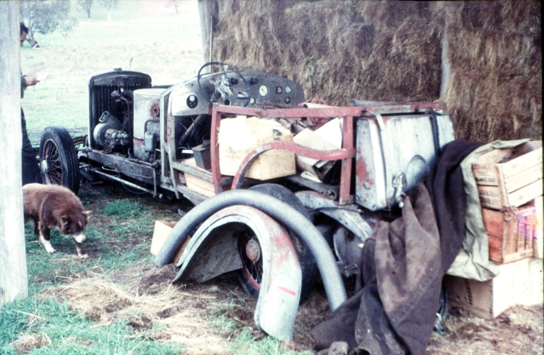   Capacitive Water Level Gauge: Assembly Notes Part Two Probe The probe is an insulated thin wall brass tube. The insulation I have used is Teflon (PTFE) heat shrink tubing. To prevent some problems experienced with earlier versions, the brass tube should be perforated about every half inch. I suggest rotating the tube while heating the heat shrink tubing to obtain uniform shrinkage. I have tried several samples of heat shrink tubing and think McMaster-Carr catalog number 75665K62 is particularly suitable. A four foot length costs less than eight Dollars. A second method of insulating the probe is to wrap the tube with overlapping layers of teflon tape made for pipe joint purposes. I have not tried this method, but it has been used successfully by another user of this gauge. Probe Mounting The bottom end of the probe is inserted in a Teflon insulator which is in turn inserted in a drilled hole in a quarter inch brass pipe plug. Red high temperature silicon rubber joint compound seals the probe from water leakage. As the probe is open at both ends, the silicon rubber is not required to be pressure resistant. The top end is centered by its contact wire on the sparkplug used as the gauge's signal connector. I have used both the Autolite 4194 and the Champion J99, which is an industrial furnace igniter. The Champion is both easier to use and more reliable, it having a long electrode to which it is easy to braze an extension. The extension serves only to make electrical contact with inside of the probe tube and may be as thin as twenty gauge copper wire. A few slight bends in this wire will insure adequate contact. As the usual spark plug gasket works poorly with steam and to obtain a grounding point for the cable, an O-ring retainer made of a tenth inch thick brass or steel is fitted on the plug. If the seat hole is 0.75 inch diameter, a 206 Viton O-ring will work. The grounding point is tapped 6-32. Sensor Case I have used a length or one inch black iron pipe with ends and suitable connections welded on. The ends may be made of three eighths thick steel plate. A 1 1/2 inch hole saw can be used to make the end pieces. The top end can be tapped to take the sparkplug directly, 14 by 1.25 mm. thread for the Champion plug. The bottom end should be tapped one fourth National pipe thread. The side fittings may be five eighths round steel rod, or short bits of 1/4 inch black iron pipe.. Drill them and the body of the gauge one fourth of an inch so a bit of threaded rod will hold them in place during welding. Afterwards, they can be drilled five sixteenths and tapped one eighth pipe thread. For a ten inch gauge, a twelve inch length of pipe is suggested. Thus the side fittings can be an inch from the end and still be ten inches apart. Assembly To keep the probe centerd while inserting it in the case. I used a long piece of thin (18 gauge) steel wire inserted first. After the bottom fitting is in place, the steel wire sticking out of the top hole will keep the probe tube in view. One may then insert the end of the connector wire in the probe, remove the steel wire and screw the sparkplug home, remembering to have the ground connector and O-ring in place first. Checking An assembled gauge should have an infinite electrical resistance whether empty or full of water. The empty gauge should have a low capacity, probably about thirty picoFarads. When full of water, the capacity should be roughly ten times as great. If the gauge is over filled so the water goes above the end of the insulated probe, it will short out and have a relatively low resistance. This will cause no damage either to itself or the circuit to which it is connected. As soon as the water level drops and the plug insulator dries, the gauge will work normally. Calibration The circuit board has two potentiometers on it for calibrating the gauge. with the gauge connected but empty, adjust the potentiometer marked R2 so the meter reads zero. With the gauge full of water, adjust the potentiometer marked R4 so the meter reads full scale. Stanley steam car Mixing Tube Fires10/16/2020 Stanley Mixing Tube Fires by Pat Farrell (aka SSsssteamer) SACA
NW Steam Clinic September 27, 2019 What are mixing tube fires? The mixing tubes of the Stanley steam car are where the vaporized fuel and atmospheric air mix to produce a combustible flame to fire above the burner grate. When the fire presents itself below the burner grate in the plenum, or in the mixing tubes below, that is not acceptable. This generally is called a mixing tube fire. What are the causes? Most common tube fires are started by a fire leak from around the burner to boiler seal. The pilot light inspection hole not being fire tight, as well as the super heater exit at the rear of the burner can also start mixing tube fires. A fuel flooded mixing tube fire is usually caused by a flooded burner. The flooded burner can be flooded either by the main fuel jets, or by the pilot light being out causing raw fuel to build up in the mixing tubes and plenum. Mixing tube fires can also be started by forcing the burner too fast at firing up and flooding the burner with raw fuel. Instead, preheat well and build a slow hot fire. Tube fires can be caused by the fire dropping down out of the burner and into the plenum by the way of a cracked burner grate. The burner’s slots or its drilled holes can become too big and therefore dropping the fire down through them and into the plenum. A warped or heat damaged burner grate can be the cause for the over-sized slots. The burner grate’s plenum not being sealed tight enough around the burner grate, can also allow the fire to descend into the plenum. Flooding of the burner plenum can be caused by using too heavy of fuel for the too large of main jets being used. Thin your fuel with gasoline or reduce the size of your jets to help reduce fuel flooding. This flooding is also a problem found at higher elevations where the oxygen is thinner. Sometimes, old fuel will refuse to vaporize, and until that fuel is disposed of, the old fuel will be a problem. Partially plugged main jets can cause drooling that will accumulate creating flooding of the mixing tubes. Misaligned main fuel jets within the mixing tubes can flood a side of a mixing tube and thereby flooding the mixing tubes. Also a resulting fog of vaporized fuel blowing back outside of the mixing tube can result in a puddle of raw fuel and an eventual tube fi re. The main jets vapor spray should always do a perfect bull’s eye inside of the mixing tubes. What should be done? A roaring mixing tube fire should be extinguished as soon as possible to prevent further damage to the Stanley burner grate. The first thing to do is to eliminate the fuel source by turning off your main burner valve. If I have a roaring tube fire, I prefer to quickly pull off of the road and try to let the excess fuel burn itself off in a small flame. Continued driving fans the tube fire making it a hotter tube fi re and possibly doing excessive damage to your burner grate. Sometimes if my mixing tube fi re gets too large, I will use my Halon fire extinguished to keep the fire from getting too big and doing collateral damage. Never use a powdered fire extinguisher in your mixing tubes as that will plug your burner grate up solid with extinguisher powder. To resume firing properly, the excess fuel has to be burned off, so a smaller fire is encouraged into eliminating the excess fuel. If the burner has lost its fi re and it is blowing raw fuel fog into the air, turn the main fuel valve off immediately and drive until the fueled smoke screen has subsided and then pull over to relight the burner. The first lighting attempt is to light the fire from the top at the smoke bonnet’s access door. To prevent your body from being burned, stand upwind from the fuel vapor cloud when lighting. Next is to check your pilot light at the peek hole for being lit. Light the pilot light if it is still out. What is the collateral damage? Too much roaring burning of a mixing tube fire will eventually crack your burner grate. Plenum fires can also destroy all of your refractory materials located in your burner. Excessive tube fires with fuel left uncontrolled can eventually burn your Stanley up. Always shut off your main fuel valve when leaving your Stanley unattended. Try to shut off your main fuel valve a quarter mile before arriving at your destination. That should clear out any stored fuel in your steam automatic system and prevent your main fuel from later cycling on and drooling fuel while the Stanley is parked. What can be done to continue driving while tube fi res persist? Sometimes while on the road, a quick fix for tube fires is just not available. To survive this problem and to continue driving, these steps can be taken. Reduce your fuel pressure so as not to create too much internal pressure inside of the burner/plenum area. Reducing your fuel pressure to below 100 PSI can sometimes get you home. Get your Stanley rolling up to about 18 MPH or faster before slowly turning on your main fuel valve. This creates a draft so as to keep the fire burning above the burner grate and not in the plenum or mixing tubes. Some Stanley's have a stack blower that can be used to duplicate this need for a draft. Before using your main fuel valve, by using your firing up valve you can gently bring your fire temperature up to a good firing rate following with firing with the main fuel valve. If your burner grates become sooted up from tube fires and it restricts the passage of the air/fuel vapor, remove your main fuel jets and if you have one, use your steam enema with full steam to clear your burner grate of any soot. I have also removed my smoke bonnet, and by blasting down each fire tube with an air nozzle, I cleared the sooted up the burner grate below of its blocking soot. Once I was in a blinding dust storm that blocked my burner grate with dust. My steam enema saved me that day too. Hopefully something in my above SSsssteamer experiences will help you in your steam car adventures. < From bill Bill Lloyd 2011 Only today I had actually made a start at sorting through all my own Dungog photos, apart from just picking out a few here and there – like the ones attached. I still have hopes of making a disc of all my rally photos of the past decade, but something always seems to interrupt the process. I’m sure it will happen, eventually. The Model K was delivered here to Denistone in Sydney to give me more time to “bond” with it. It’s been stone cold since it left Dungog, but we’ll be taking it out again on Friday so a couple of friends from the Road Steam Engine Association can have a ride and officially certify it for its annual club registration. The Doble went back to Trevor’s for some new plumbing. Trevor’s currently on holidays somewhere in central NSW for a few weeks. I nearly killed myself getting ready for the rally. Now I’m killing myself catching up afterwards. One of my friends went to London on Sunday. Another left for Japan today. He asked if I wanted to go with him, as I did once in the past, but alas, I’ve used up all my leave points for a while. I’ve asked the body people to get me the Model K paint colour code which Basil wanted, so please tell him it will be forthcoming in due course. They’re currently working on the 1915 Detroit electric, which was dropped off in the same truck which then loaded the Model K for Dungog. The Detroit springs and wheels need stiffening up in a few places, with powder coating on the wheels. Incidentally, I made contact with your friend Don Davidson, first to buy a reproduction motor plate for the Detroit and then to see about having some Doble hub cap badges made. I told him how much I had enjoyed both the articles you sent me about his Detroit and Stanley. Best regards to you both Bill THE RUSHCOMBE GENTLEMANS STEAM BIKE BY MARK DRAKE Part Three   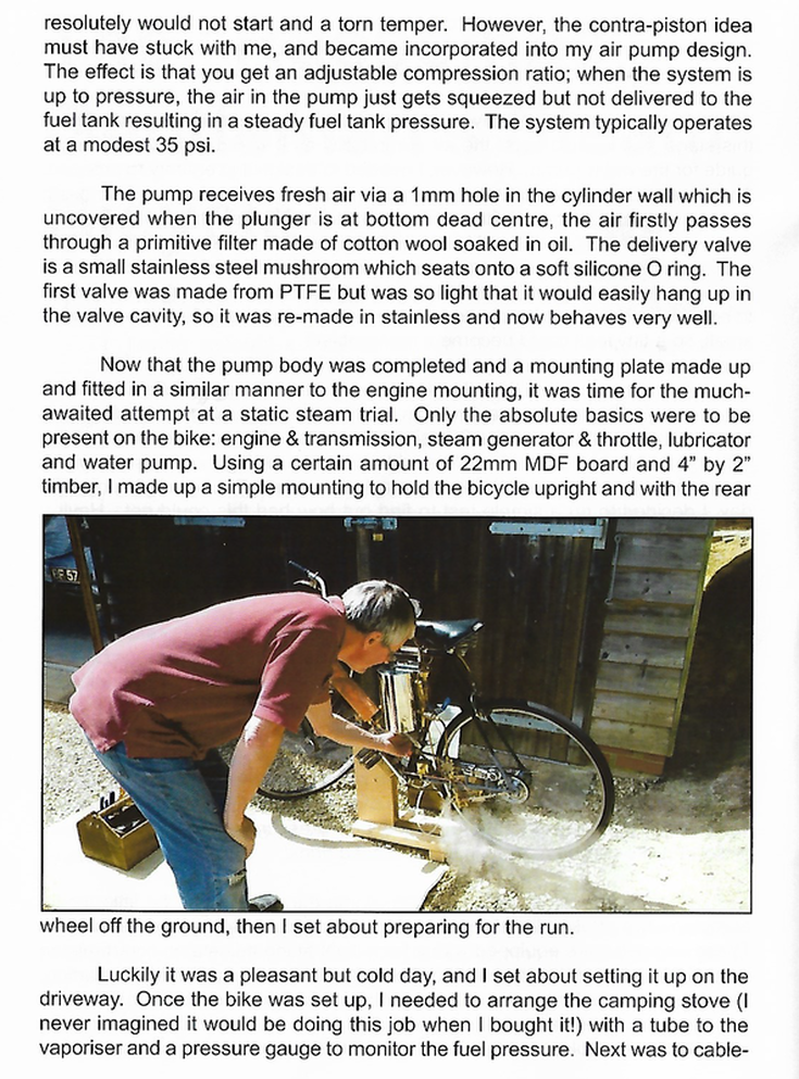    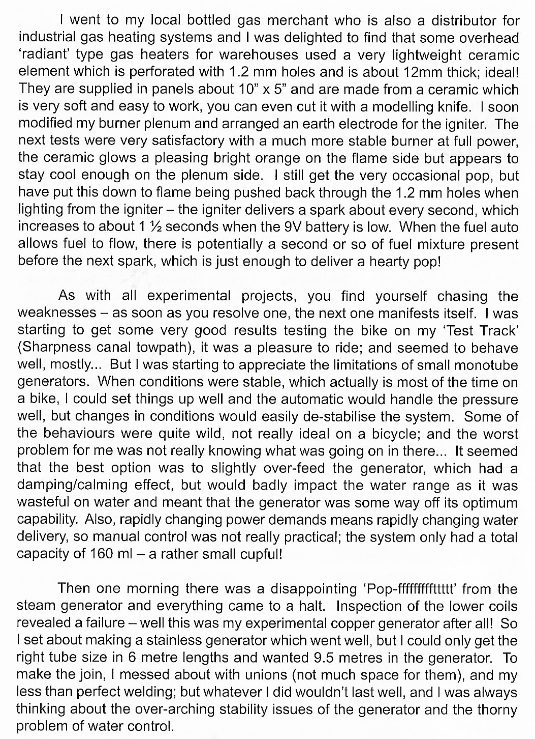 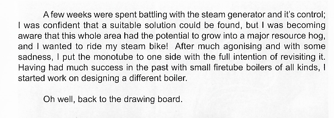    THE RUSHCOMBE GENTLEMANS STEAM BIKE BY MARK DRAKE Part Two    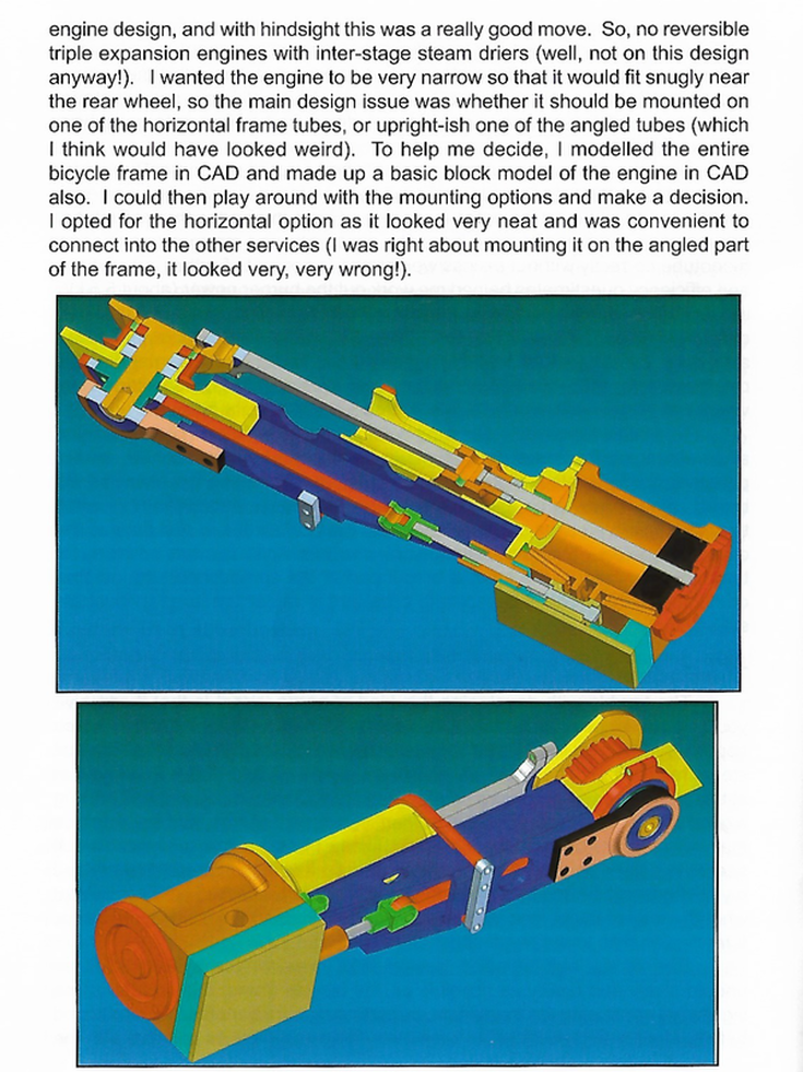 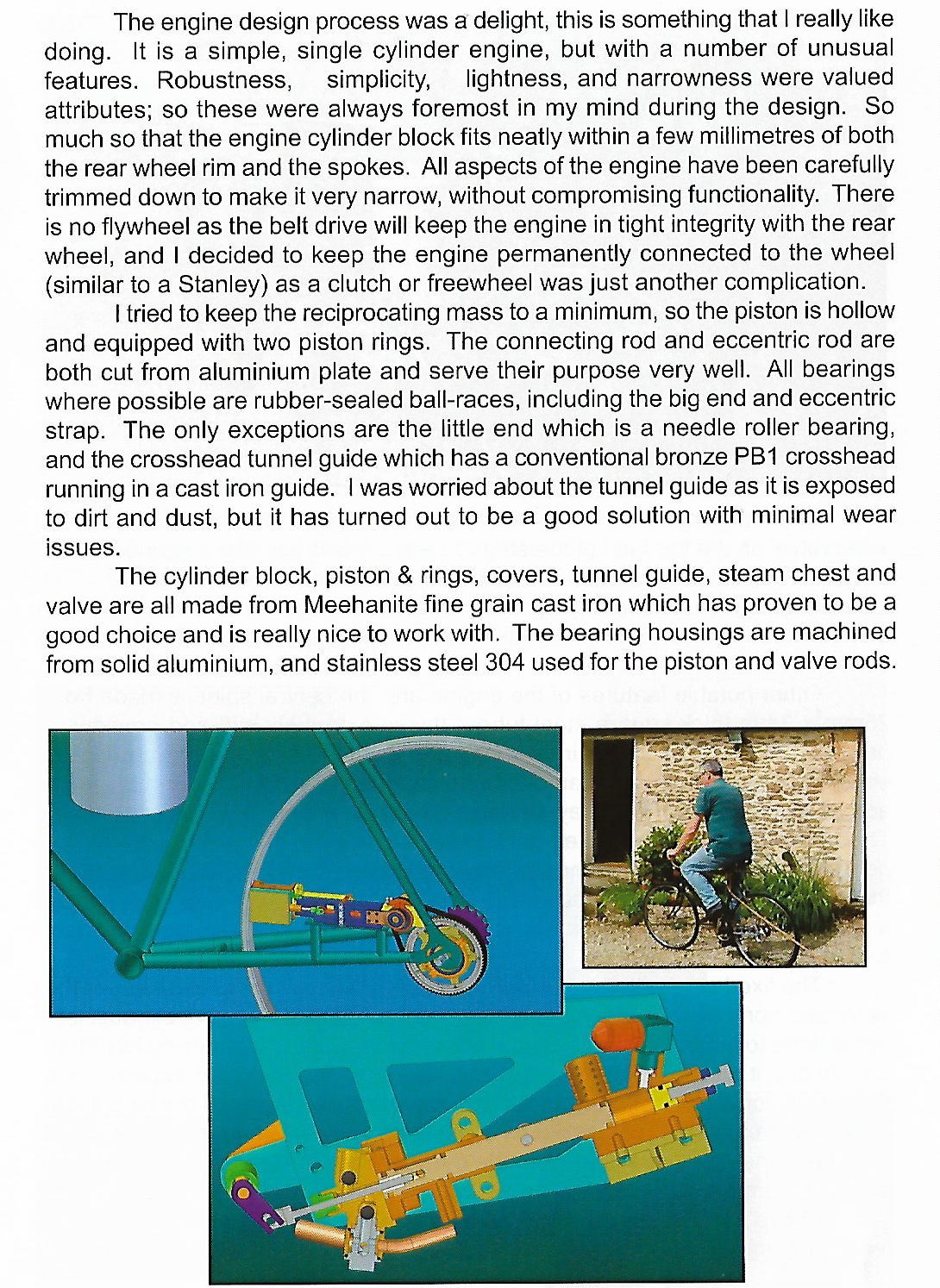 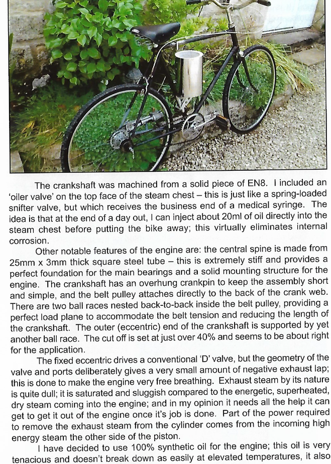 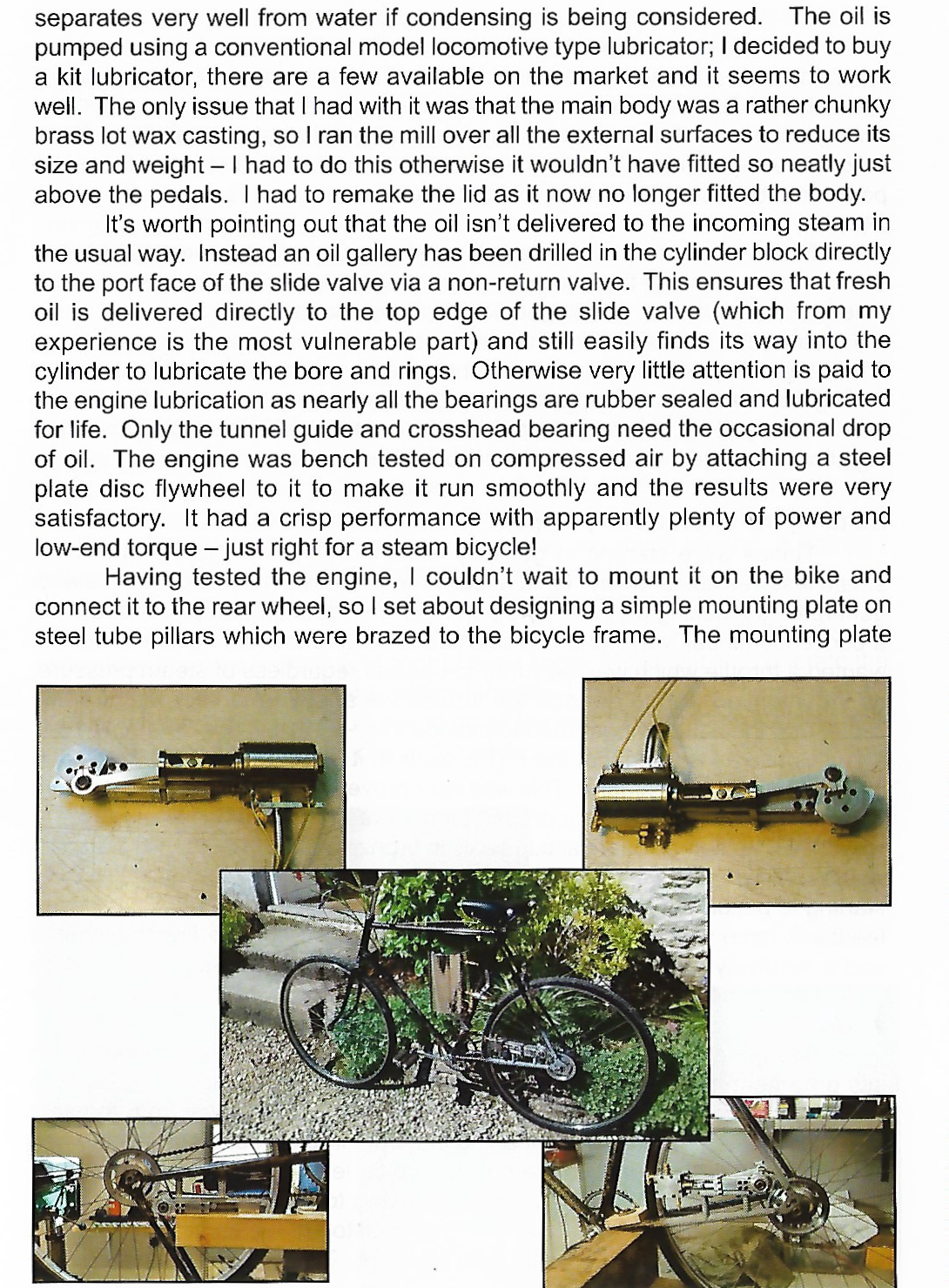    |
Archives
December 2022
Categories
All
|
 RSS Feed