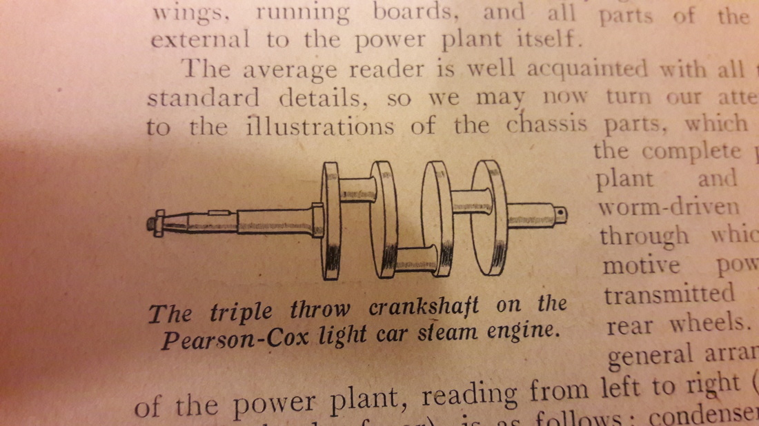
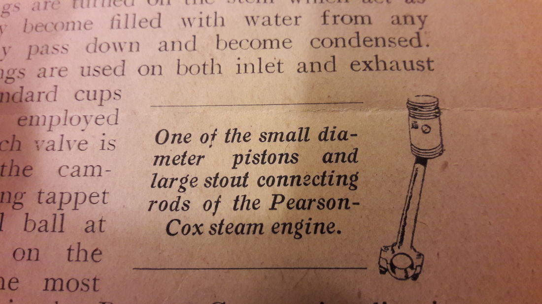
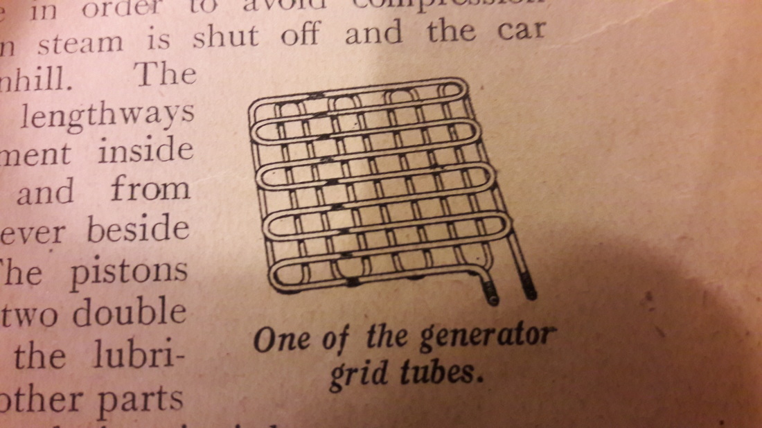
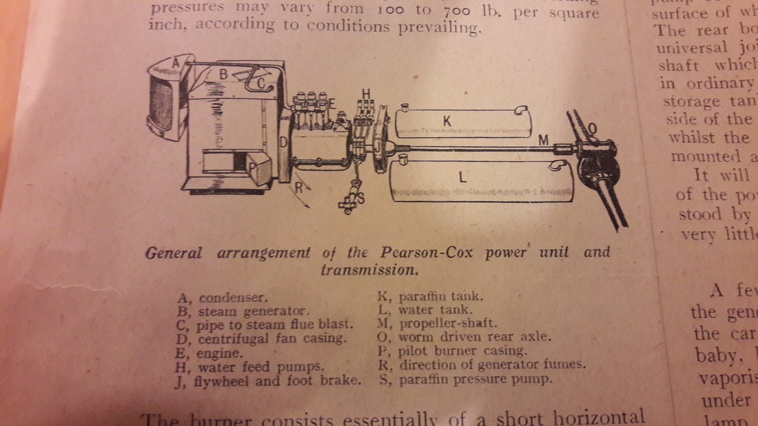
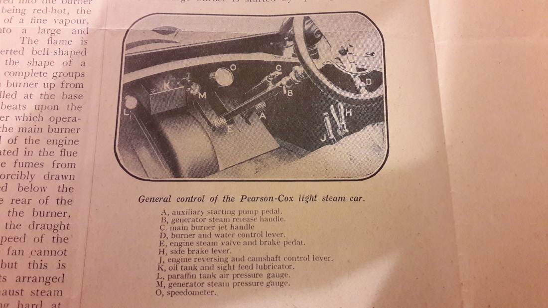
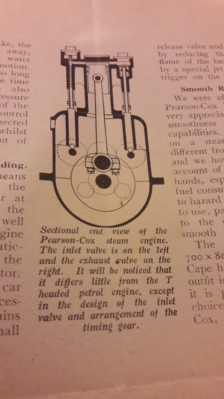
Steam Cars From the Archives-Pearson-Cox11/19/2016 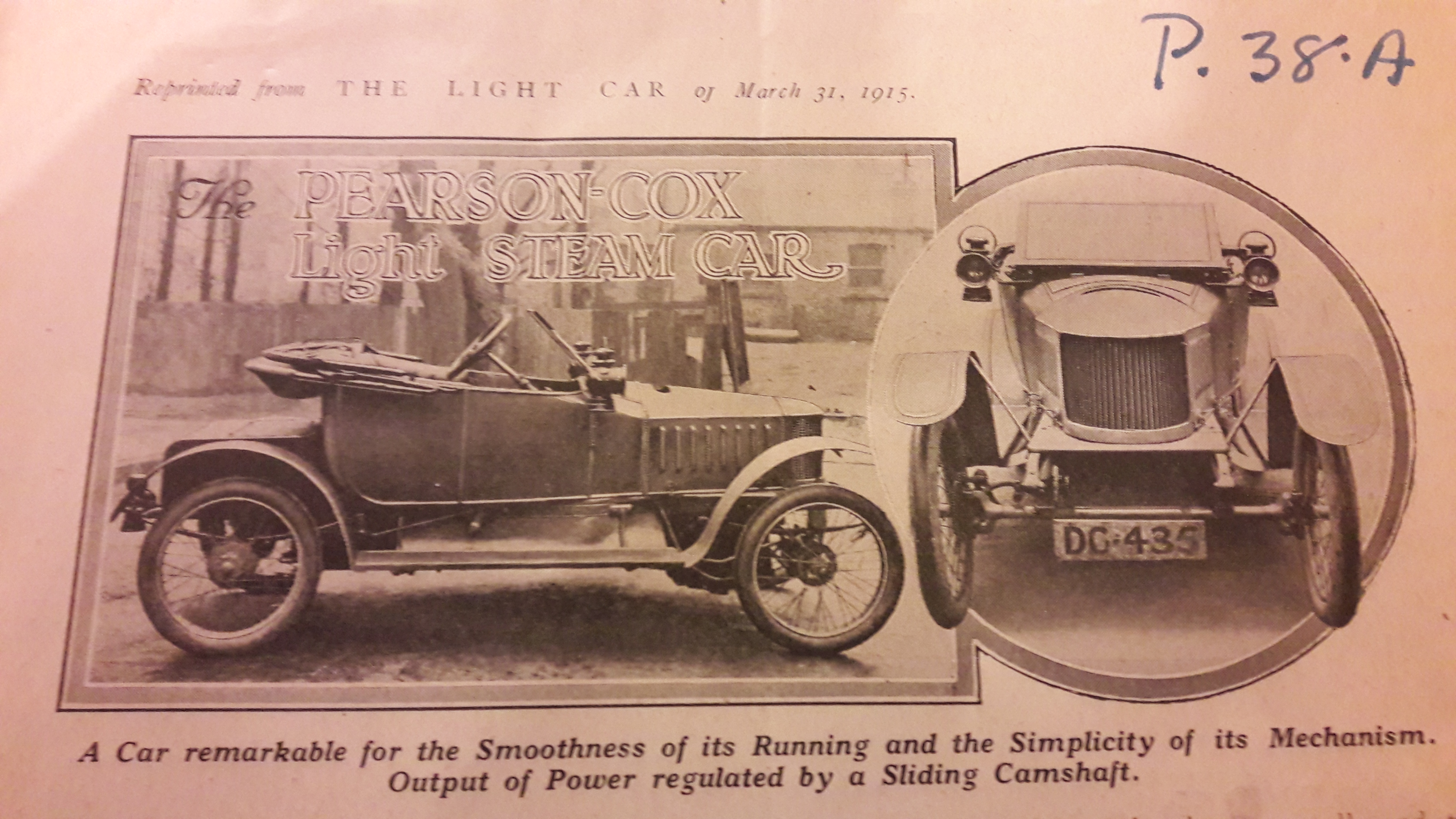 Reprinted from The Light Car of March 31st 1915. The vehicle we are about to describe is a small edition of the larger Pearson-Cox steam-driven automobiles, which have been well known on the market for some years past. One may, therefore, rest assured that the latest Pearson-Cox light steam car is not by any means an experiment in view of the experience which the constructors have accumulated in producing this type of vehicle since it first came in. In this firm's light steam car, the frame, axles, wheels, and springing system are of standard pattern, the same applying to the body, wings, running boards, and all parts external to the power plant itself. The average reader is well acquainted with all these standard details, so we may now turn our attention to the illustrations of the chassis parts, which show the complete power plant and rear worm-driven axle through which the motive power is transmitted to the rear wheels. The general arrangement of the power plant, reading from left to right (or from front to back of car), is as follows: condenser, steam generator, draught fan, engine, water and fuel supply pumps, foot brake, propeller-shaft ( on either side of which are the fuel and water tanks), and rear axle, each of which will now be referred to in detail. The Three-cylinder Engine. The engine has three small single-acting cylinders of 1 3/4 in. bore by 3 in. stroke, cast monobloc, with a three-throw crankshaft having the crank pins at intervals of 120 degrees. This crankshaft is cut out of a solid bar of steel, and is a remarkably fine piece of work. Each cylinder has its inlet and exhaust valves arranged in T-head manner, and operated by a pair of camshafts arranged on either side of the crankshaft in the crank chamber. Owing to the high pressures of steam used, the inlet valve is very small, and to prevent the steam leaking past the valve stem a number of shallow rings are turned on the stem which act as glands as they become filled with water from any steam that may pass down and become condensed. Very light springs are used on both inlet and exhaust valves, and standard cups and cotters are employed below them. Each valve is operated from the camshaft through a long tappet which has a steel ball at its base bearing on the cam. One of the most interesting features in the Pearson-Cox engine lies in the sliding camshafts, which are arranged with different sets of cams in order to provide, besides a reverse gear, a varying lift both for the inlet and exhaust valves, so that the expansion of steam in the cylinders (and therefore output of power) may be varied from the driving seat. as well as allowing all the exhaust valves to be lifted at once in order to avoid compression in the cylinders when steam is shut off and the car running free downhill. The camshafts are moved length-ways by a toggle arrangement inside the crank chamber, and from there connected to a lever beside the driver's seat. The pistons are each provided with two double step cut rings, whilst the lubrication of these and all other parts of the engine is on the splash principle. The Steam Generator. Immediately in front of the engine is the steam generator. This is composed of a number of horizontal tube grids connected up with union joints made of extremely stout steel tubing tested to 7,000 lb. per square inch. Numbers of these are suspended within a sheet steel casing at the base if which is a large paraffin burner and draught-pan. A small quantity of water is forced into the lower grid, flashing into steam, immediately, and thence it travels upwards to the top grids, returning via the central grids to the engine in a highly super-heated state. The quantity of water that exists in the red-hot generator grids at any time is extremely small, whilst the working pressures may vary from 100 to 700lb. per square inch, according to conditions prevailing. The burner consists essentially of a short horizontal coil of steel tubing connected to a special form of jet just below it. The parrafin is fed into the burner under pressure, and the coil tube being red hot, the oil issues from the jet in the form of a fine vapour, which, when lighted, develops into a large and extremely powerful blast of flame. The flame is arranged to impinge against the shape of a chrysanthemum, and spreads over the complete groups of generator grids. To start the main burner up from cold, a baby paraffin burner is installed at the base of the generator, so that its flame beats upon vapourising coil of the main burner, after which operation it is shut off altogether as soon as the main burner is efficiently working. The front end of the engine crankshaft carries a centrifugal fan situated in the flue extension of the generator, so that the fumes from the upper end of the generator are forcibly drawn down through the flue and discharged below the chassis to be finally carried away at the rear of the car. Forced draught is thus given to the burner, which renders it doubly efficient, but, as the draught depends in this case entirely upon the speed of the engine and fan, it is obvious that the fan cannot be sufficiently powerful at low speeds, but this is ingeniously counteracted by a row of jets arranged inside the flue which are fed from the exhaust steam pipe, so that, should the engine be pulling hard at low speeds on a hill and the generator requiring fully forced draught to maintain a good head of steam, the high exhaust steam pressure from the engine gives a correspondingly greater flue draught through the increased velocity of steam through the jets. The Lay-out of the Chassis. The rear extremity of the engine crankshaft between the flywheel and crank chamber carries three small eccentrics which are arranged to operate a triple throw set of pumps for the generator water feed, and also a pump for delivering paraffin under pressure to the burner supply tank. These can be seen in our sketch, but the necessary piping in the vicinity of the generator, engine, pumps, and supply tank has been omitted to obviate confusion. Immediately behind the pump eccentrics is the engine flywheel, on the outer surface of which acts the contracting band foot brake. The rear boss of the flywheel carries a sliding type universal joint to which is connected the propeller-shaft which drives the worm-driven back axle as in ordinary car practice. Both paraffin and water storage tanks are carried in a neat manner on either side of the propeller shaft, as shown in the illustration, whilst the condenser for cooling the exhaust steam is mounted at the extreme front of the chassis. It will thus be seen that the general arrangement of the power plant is quite simple and readily understood by the comparative novice who may have seen very little of the steam car previously. Starting up from Cold. A few details regarding the operation of starting the generator up from cold and the manner in which the car is driven may be of interest. The pilot, or baby, burner is started up to heat the main burner vapourising coil by lighting a little methylated spirit under it in the same manner as with an ordinary blow lamp. When the main vaporising coil has become red-hot, the large burner is started by opening the main parrafin valve, after which it is left for a few minutes to heat up the generator tube grids. When the generator is fully heated the pilot burner is shut off, and the driver installs himself in the car, and proceeds with his foot and right pedal to inject (with a small auxiliary pump) a small quantity of water into the generator, which is instantly flashed into steam to a pressure of, perhaps, from 200 lb. to 300 lb. per square inch, as shown by the gauge on the dashboard. On releasing the right pedal, which is connected to the main steam valve and foot brake, the engine immediately starts away, and in doing so sets the main water feed pumps to the generator in motion. The water feed is thus automatic so long as the car is moving. At the same time the engine-driven paraffin pump also automatically feeds a burner pressure tank. The steam-raising powers of the generator are regulated by a control lever on the steering wheel connected to the burner main supply valve, whilst it also partly regulates the amount of water fed to the generator. Engine Running when Car is Standing. Besides varying the power by means of a pedal, the flexibility of the engine is also regulated by a lever at the side of the driver connected to the sliding camshafts of the engine, as well as operating the reversing of the engine and car. The oil is fed semi-automatically to the engine from a tank on the dashboard and a sight feed lubricator. When it is desired to leave the car standing for some time it is only necessary to release what little steam remains in the generator by opening a small release valve and to shut down the burner by reducing the paraffin feed. The flame of the burner can also be reduced by a special jet arrangement operated by trigger on the steering wheel column. Smooth Running of a Steamer. We were afforded a short run on the Pearson-Cox light steam car, and were very appreciably impressed by its unique smoothness of travel and hill-climbing capabilities. The sensation of a spin on a steam car is something quite different from driving a petrol-driven car, and we hope to give our readers a full account of a run with the car in our own hands, especially in regard to water and fuel consumption. We should be inclined to hazard a guess that such a car is cheap to use, particularly as regards tyres, owing to the even propulsion and the very smooth take up of the drive. The price of the complete car with 700x80 mm. tyres, adjustable screen, Cape hood, side and tail lamps, and tool outfit is £185, whilst the colour in which it is painted is left to the customer's choice. The makers are Pearson and Cox, Ltd., Shortlands, London, S.E.
2 Comments
Leave a Reply. |
For instructions on how to add to our community's blog post, please visit our Get Involved page by clicking on the link above!
Archives
November 2022
Categories
All
|
 RSS Feed
|
|
Steam Car Network functions as a resource for all steam car and steam bike enthusiasts. The website is constantly updated with articles, events, and informative posts to keep the community alive and growing. Feel free to contact us if you have any questions or concerns at the email address below and we will promptly reply.
[email protected] |
|